Hard Start, No Start, or Rough Idle in Temperatures Near or Below 20 Degrees C (-4 F) (Install New Positive Crankcase Ventilation (PCV) System)

| Subject: | Hard Start, No Start, or Rough Idle in Temperatures Near or Below -20°C (-4°F) (Install New Positive Crankcase Ventilation (PCV) System) |
| Models: | 2004-2005 Chevrolet Aveo |
| 2005 Pontiac Wave |
| with 1.6L 4-Cylinder Engine (VIN 6 - RPO L91) |
Important: This bulletin applies to vehicles sold and registered in the U.S. ONLY. Vehicles sold and registered in Canada should refer to Recall Bulletin 05521.
Condition
Some customers may comment on a hard start, no start, or rough idle condition in temperatures near or below -20°C (-4°F).
Cause
Engine throttle body operation may be affected in temperatures near or below -20°C (-4°F).
Correction
This condition will only occur when the temperature is near or below -20°C (-4°F). If this condition occurs above -20°C (-4°F), refer to Corporate Bulletin Number 05-06-01-030, or the appropriate model year Service Manual. If this condition is present when the temperature is near or below -20°C (-4°F), replace the first design PCV system with a new second design PCV system.
PCV Kit Installation
Caution: Before servicing any electrical component, the ignition key must be in the OFF or LOCK position and all electrical loads must be OFF, unless instructed otherwise in these procedures. If a tool or equipment could easily come in contact with a live exposed electrical terminal, also disconnect the negative battery cable. Failure to follow these precautions may cause personal injury and/or damage to the vehicle or its components.
- Disconnect the negative battery cable.
- Remove the air cleaner intake duct.
- Disconnect the idle air control (IAC) valve connector.
- Disconnect the throttle position (TP) sensor connector.
- Remove the coolant inlet/outlet hose from the backside of the throttle body.
- Remove the crankcase ventilation hose from throttle body. Discard the crankcase ventilation hose.
- Remove the coolant outlet hose and ABS test connector (if equipped) from the coolant surge tank side of the throttle body. Discard the coolant outlet hose.
- Remove the bottom throttle body retaining bolt. Discard the retaining bolt.
- Install the A1-PCV T/Body hose assembly, P/N 96469943.
- Install the IAC valve connector.
- Install the TPS connector.
- Install the air cleaner outlet duct. Reuse the old screw band on the second design air cleaner duct.
- Install the breather hose to air cleaner duct.
- Install the IAT sensor connector.
- Replace the oil filler cap with new oil filler cap, P/N 96469205 (from the kit).
- Connect the negative battery cable.
- Add required engine coolant to the coolant system, P/N 12378560, or equivalent (refer to SI document 1298421).
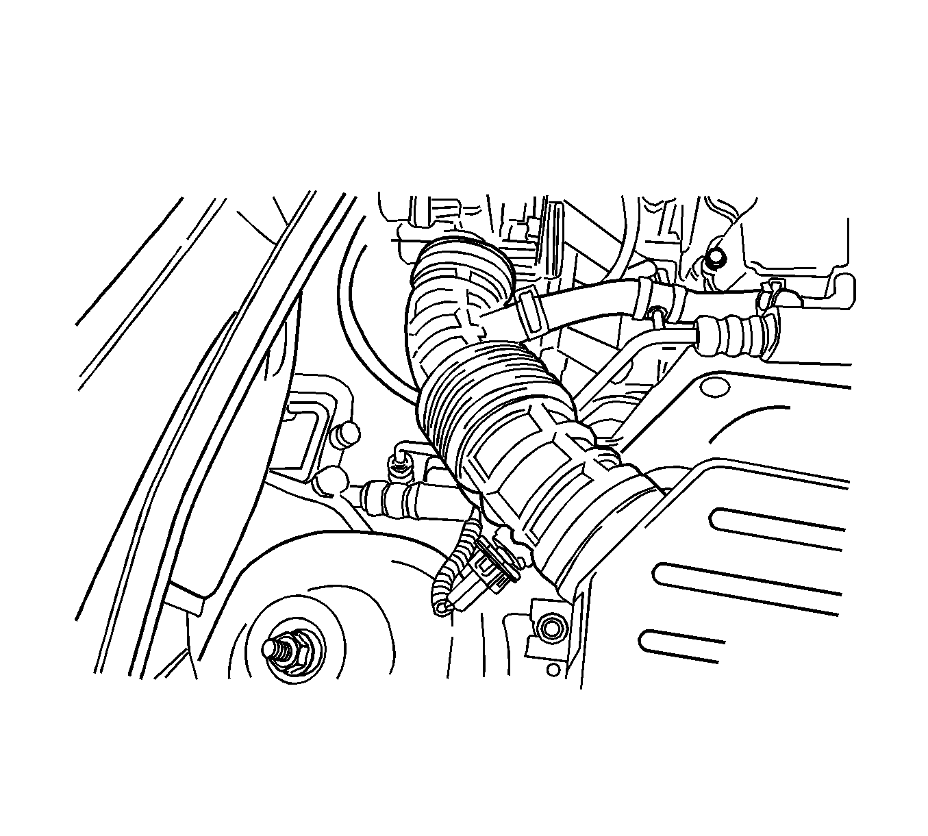
| 2.1. | Disconnect the electrical connector from the intake air temperature (IAT) sensor. |
| 2.2. | Disconnect the breather tube from the crankcase ventilation tube. |
| 2.3. | Remove the air cleaner intake duct. |
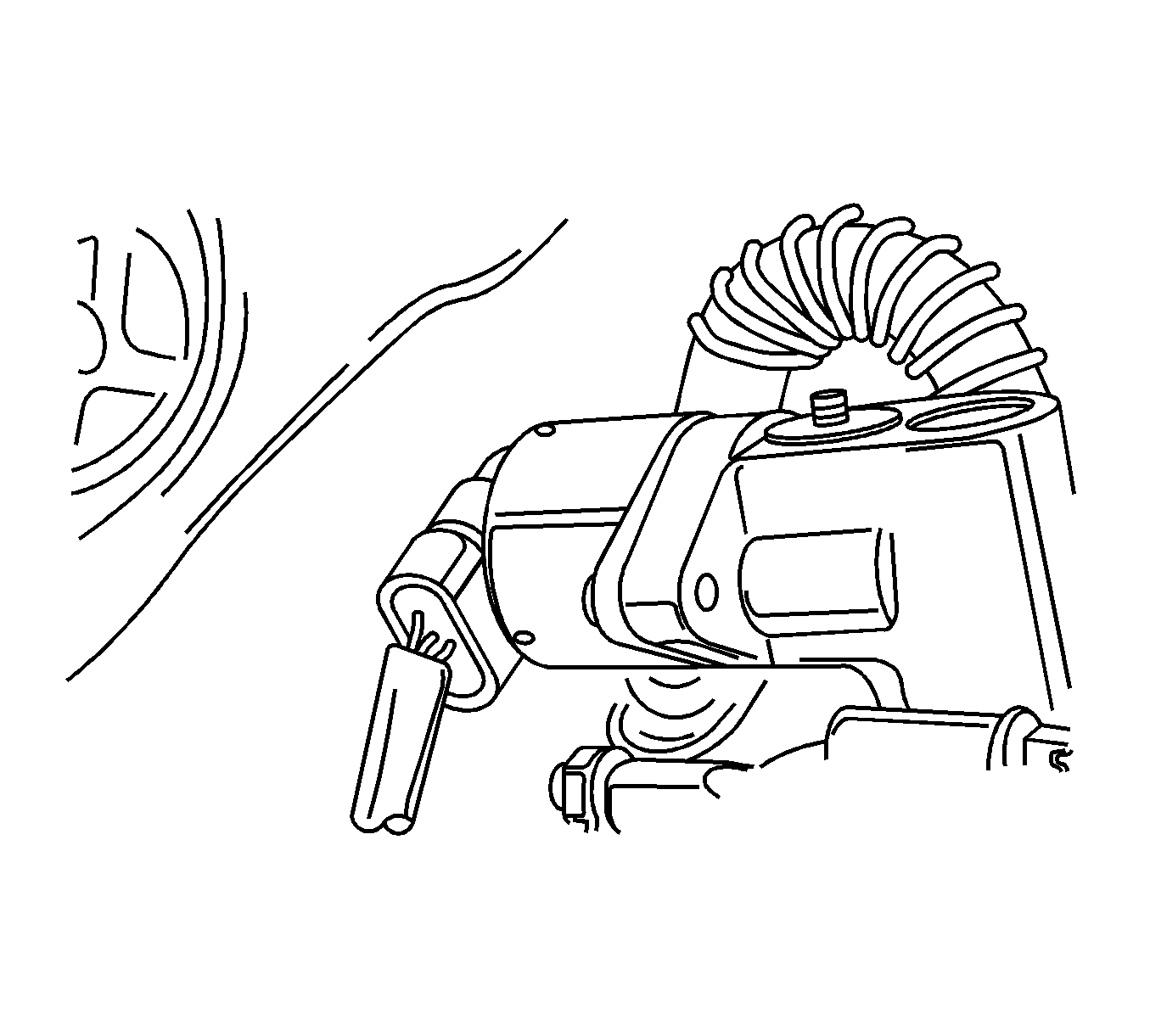
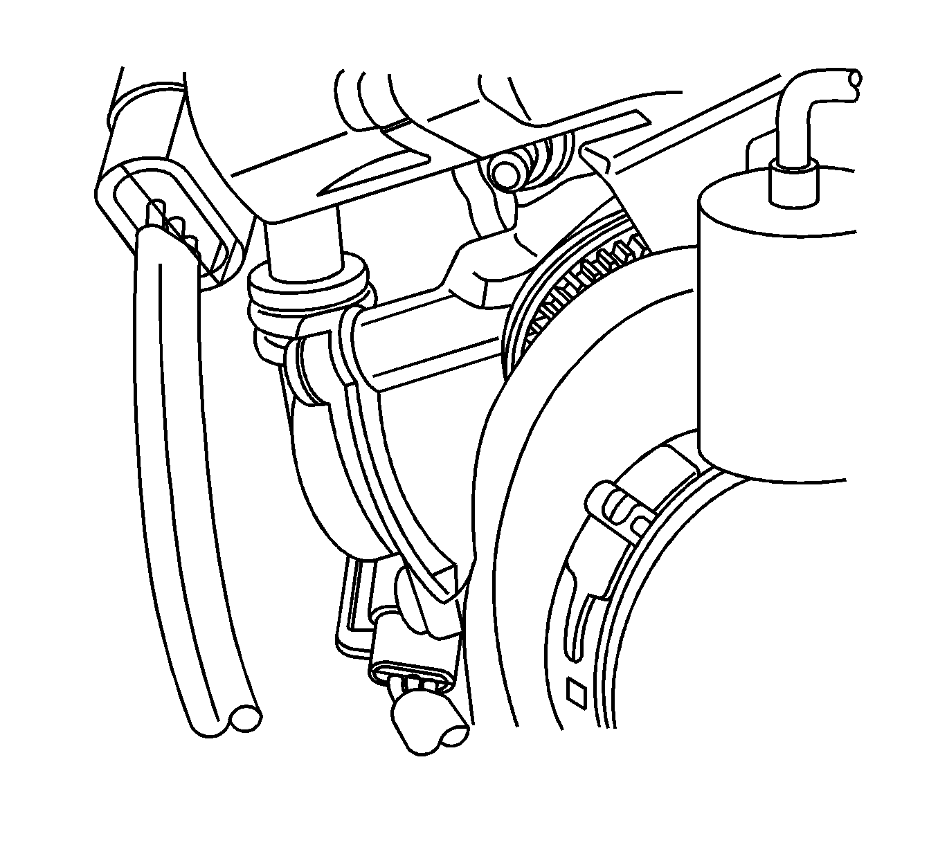
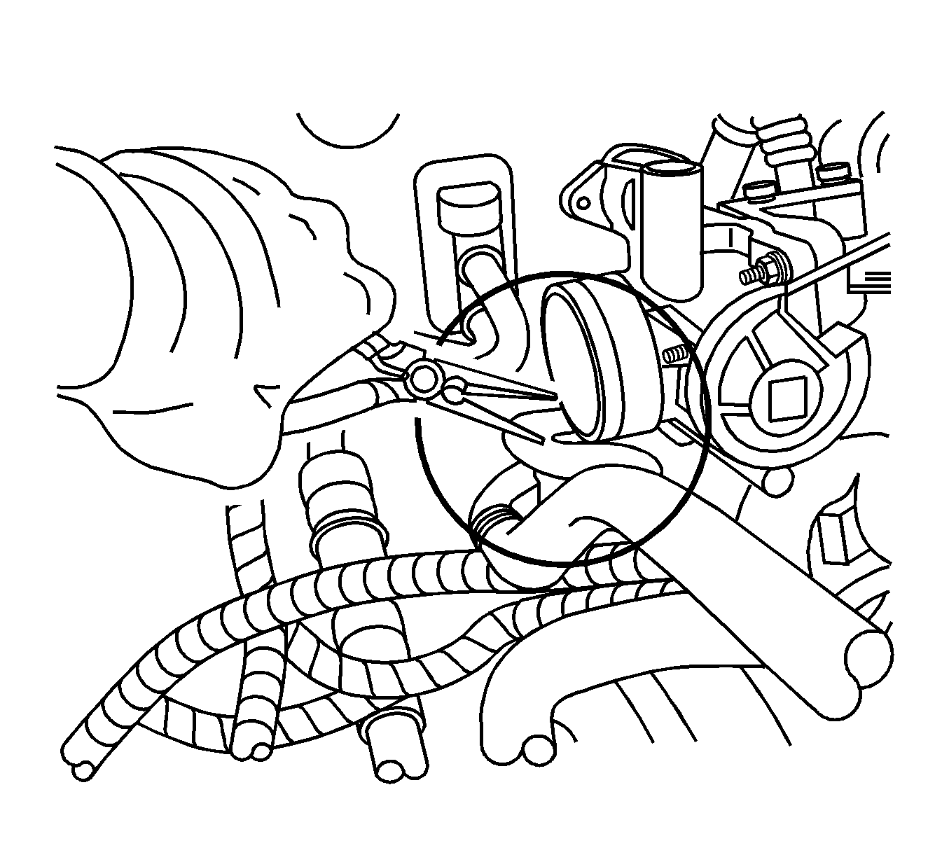
Caution: To avoid being burned, do not remove the radiator cap, surge tank cap or coolant hoses while the engine is hot. The cooling system will release scalding fluid and steam under pressure if radiator cap, surge tank cap or a coolant hose is removed while the engine and radiator are still hot.
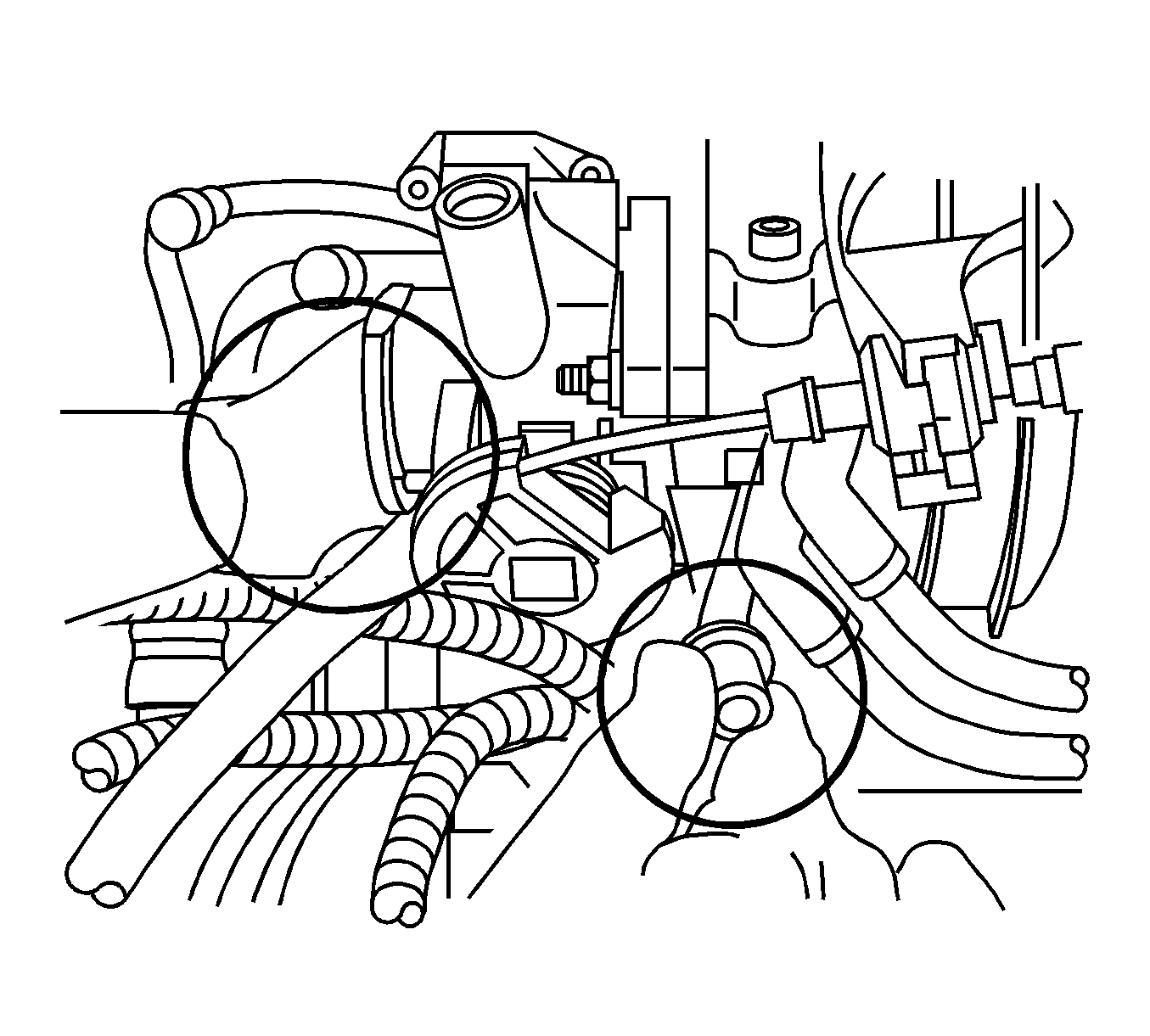
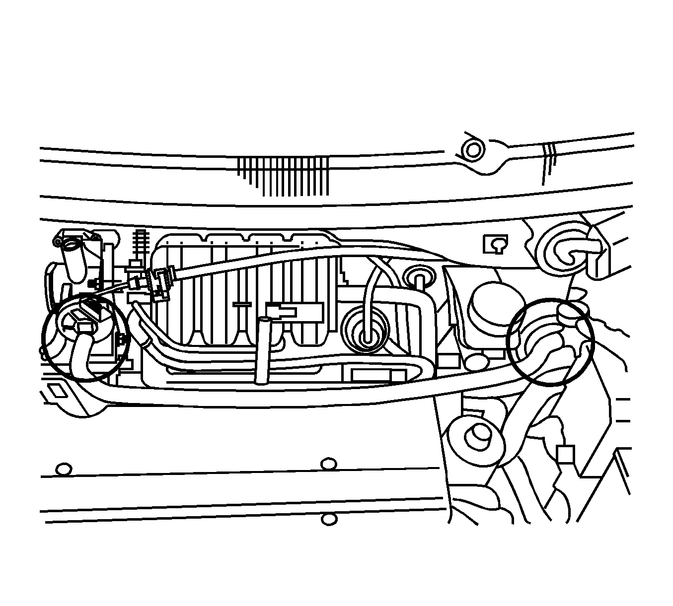
Caution: To avoid being burned, do not remove the radiator cap, surge tank cap or coolant hoses while the engine is hot. The cooling system will release scalding fluid and steam under pressure if radiator cap, surge tank cap or a coolant hose is removed while the engine and radiator are still hot.
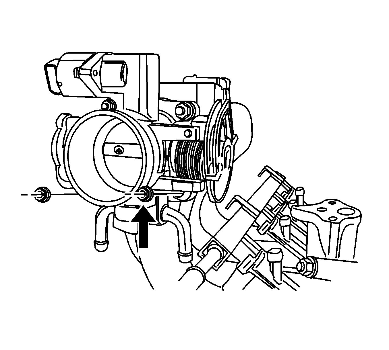
Important: Apply Super Lube® multi-purpose lubricant, P/N 12346241, or equivalent, to the inside ends of the coolant hoses and crankcase ventilation tubes before installing the A1-PCV T/Body hose assembly, P/N 96469943 (from the kit).
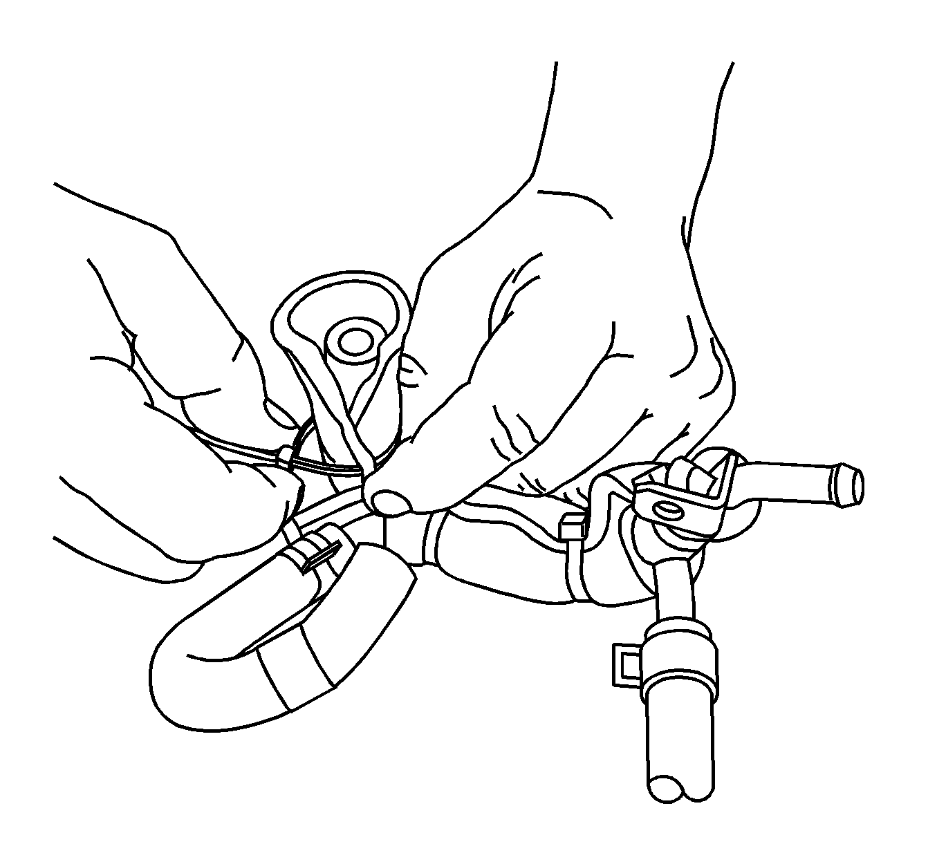
| 9.1. | Tie wrap the protective material (from the kit) around the backside of the throttle body portion of the crankcase ventilation tube of the A1-PCV T/Body hose assembly. The length of the protective material should be 10 mm (0.39 in) longer than the end of the crankcase tube. The tie strap must be located on the curved portion of the A1-PCV T/Body pipe. Do not tie wrap the hose above the curved portion of the pipe. Remove excess tie strap. |
| 9.2. | Install the A1-PCV T/Body hose assembly to the rear of the throttle body. |
| 9.3. | Install the backside of the throttle body portion of the new crankcase ventilation tube of the A1-PCV T/Body hose assembly to the pipe on the backside of the throttle body. Insert a second tie strap through the space under the throttle body in order to tie wrap the protective material near the tube opening. Remove excess tie strap. |
| 9.4. | Install a new bolt, P/N 94500416 (from the kit), through the hole of the A1-PCV T/Body hose assembly bracket. |
| 9.5. | Install the backside portion of the new coolant inlet/outlet hose of the A1-PCV T/Body hose assembly to the throttle body. |
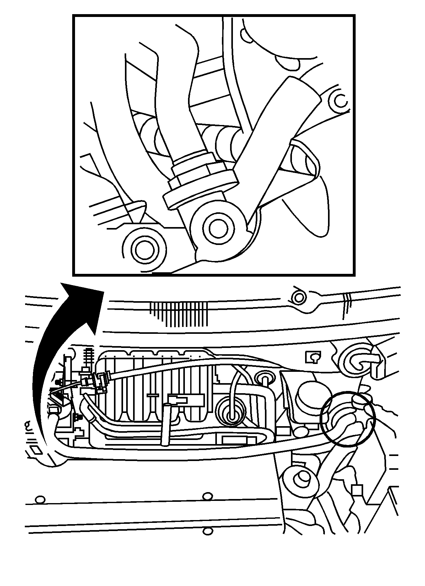
| 9.6. | Install the new coolant outlet hose, P/N 96469324 (from the kit), to the coolant surge tank and the side of the throttle body. |
| 9.7. | the crankcase ventilation hose to the cam cover and A1-PCV T/Body assembly. |
| 9.8. | Tie wrap the crankcase ventilation hose to the coolant outlet hose, P/N 96469324. |
| 9.9. | Install and tie wrap the anti-lock brake system (ABS) test connector on vehicles equipped with ABS. |
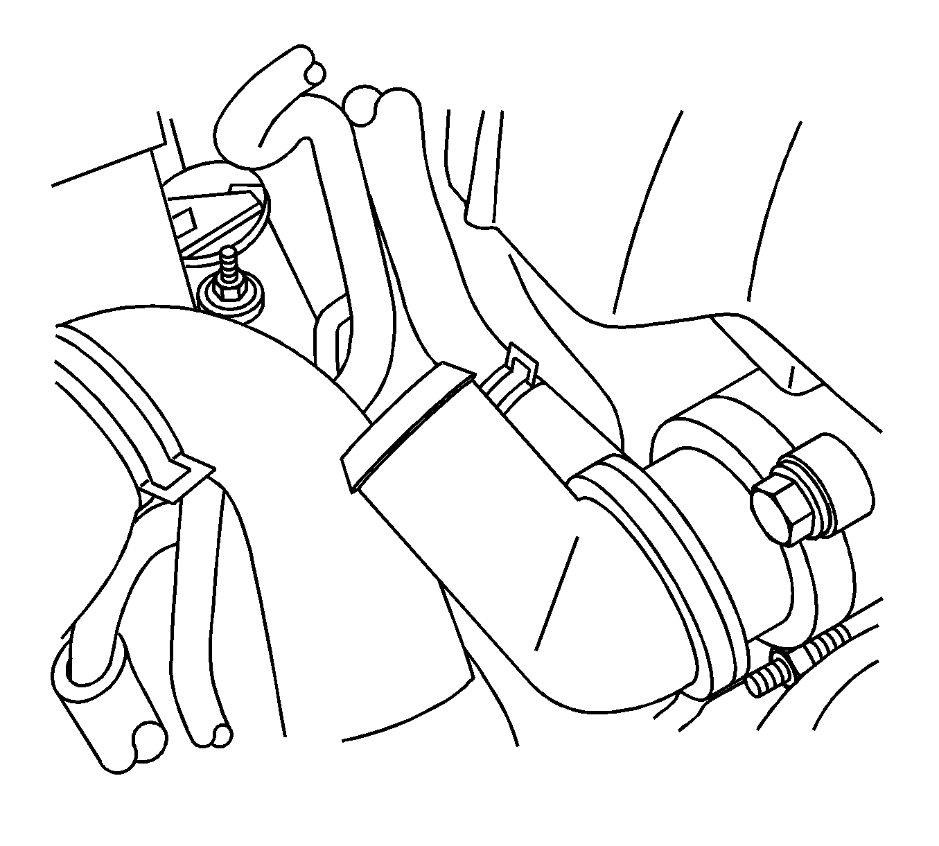
| Caution: To avoid being burned, do not remove the radiator cap, surge tank cap or coolant hoses while the engine is hot. The cooling system will release scalding fluid and steam under pressure if radiator cap, surge tank cap or a coolant hose is removed while the engine and radiator are still hot. |
| 9.10. | Disconnect the radiator upper hose at the side of the thermostat. |
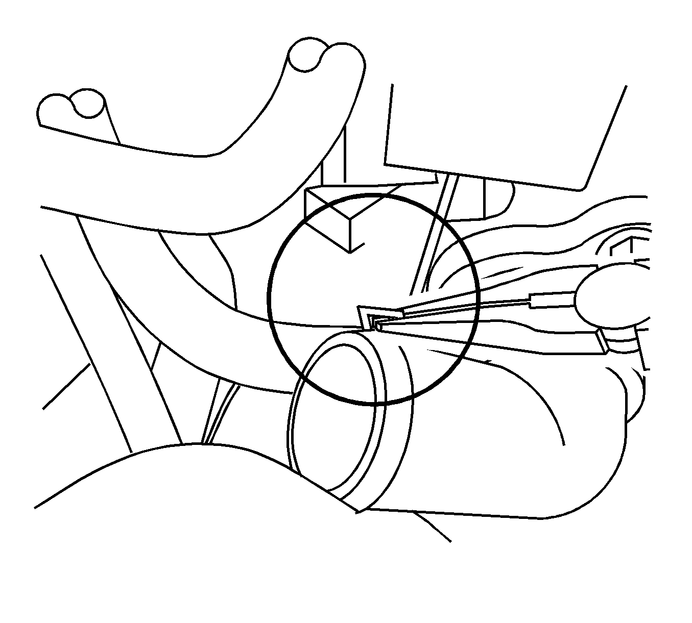
| 9.11. | Disconnect the coolant inlet hose to the thermostat. Discard the coolant inlet hose. |
| 9.12. | Connect the new coolant inlet hose of the A1-PCV T/Body hose assembly to the thermostat. |
| 9.13. | Connect the radiator upper hose. |


First Design (1) and Second Design (2) Air Cleaner Outlet Duct and Breather Hose
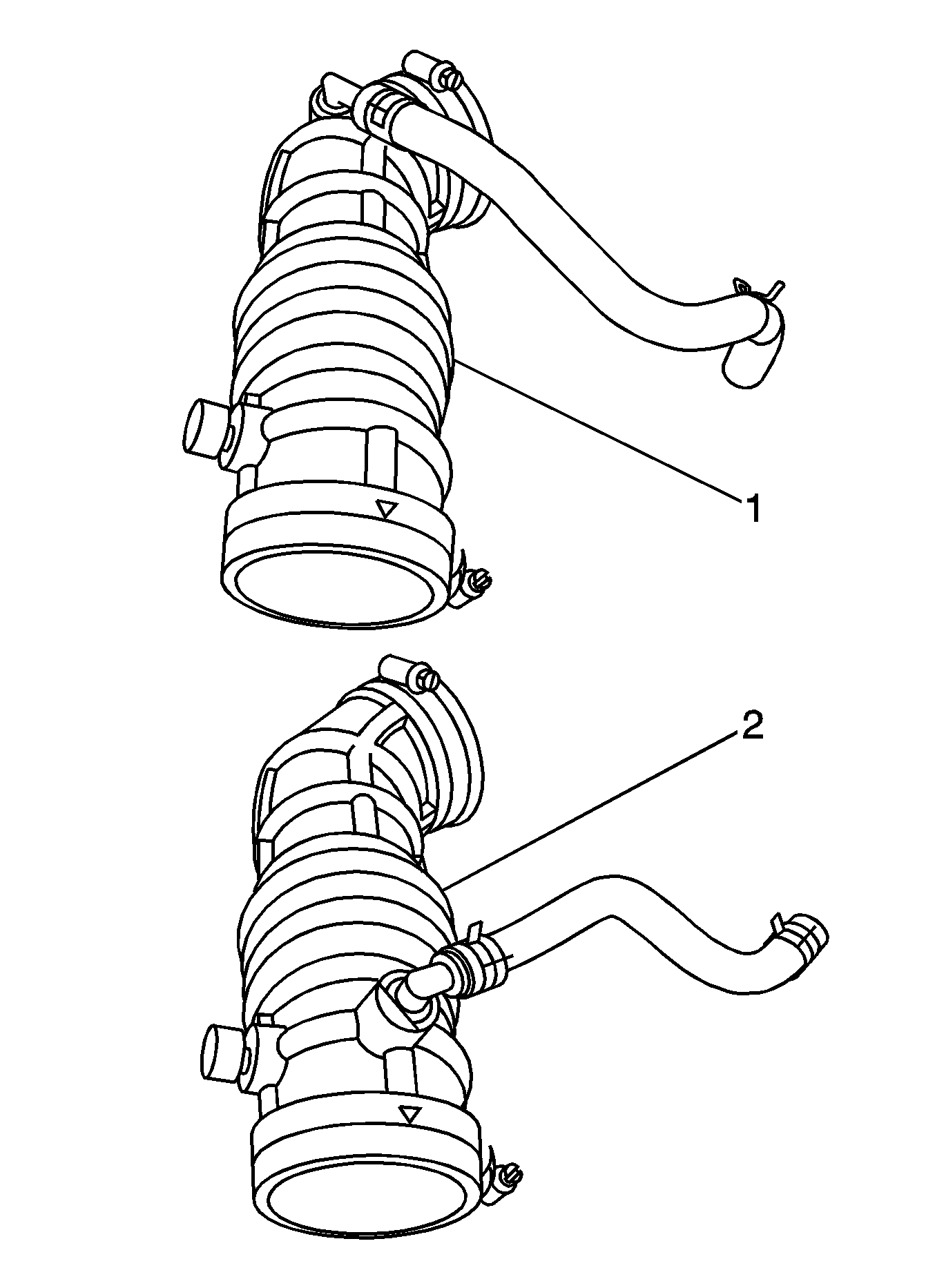
Important: Vehicles produced before December 2004 contain the first design air cleaner assembly and will require the removal of the existing air cleaner outlet duct and breather hose and the installation of the second design air cleaner outlet duct, P/N 96439858, and the second design breather hose, P/N 96437830 from kit 2. Vehicles produced during and after December 2004 contain the second design air cleaner assembly and will not require installation of the new air cleaner outlet duct and breather hose. Please use kit 1 on these later vehicles and reuse the existing air cleaner outlet duct and breather hose.

Parts Information
Important: Hose Kit 2 contains two more parts (a new design air cleaner outlet duct and breather tube) than contained in Kit 1. Compare the vehicle air cleaner outlet duct with the first and second design air cleaner outlet ducts as shown in the illustration earlier in this bulletin to determine what kit is required to complete the repair.
Part Number | Description | Qty |
|---|---|---|
96469971 | Hose A2-PCV, Kit 2 | 1 |
96469955 | Hose A2-PCV, Kit 1 | 1 |
12378560 (US) | Antifreeze, Radiator | As Required |
Warranty Information
For vehicles repaired under warranty, use:
Labor Operation | Description | Labor Time |
|---|---|---|
J7604* | Install New PCV Kit | 0.8 hr |
*This is a unique labor operation number for bulletin use only. This number will not be published in the Labor Time Guide. | ||
