Product Safety - Throttle Body Icing-Install PCV Kit (Canada Only)

| Subject: | 06515 -- Throttle Body Icing - Install PCV Kit |
| Models: | 2004-2005 CHEVROLET AVEO (CANADA ONLY) |
| 2005 PONTIAC WAVE (CANADA ONLY) |
| EQUIPPED WITH 1.6L 4-CYLINDER (RPO L91 - VIN 6) ENGINE |
This Safety Recall is a reissue of Safety Recall 05521 because the vehicles repaired under the initial service procedure may not have been repaired adequately.
Condition
General Motors has decided that a defect, which relates to motor vehicle safety, exists in 2004-2005 Chevrolet Aveo and 2005 Pontiac Wave model vehicles, equipped with a 1.6L 4-cylinder (RPO L91 - VIN 6) engine and sold in Canada. Some of these vehicles have a condition in which the engine throttle may stick open due to throttle body icing in temperatures near or below -20 degrees Celsius in high humidity environments after an initial cold engine start or while driving. If the engine throttle sticks open while the vehicle is moving, a crash could result without prior warning.
Correction
Dealers are to repair the new PCV system kit installation by following the detailed service procedure.
Vehicles Involved
Involved are all 2004-2005 Chevrolet Aveo and 2005 Pontiac Wave model vehicles equipped with a 1.6L 4-cylinder (RPO L91 - VIN 6) engine and built within these VIN breakpoints:
Year | Division | Model | From | Through |
|---|---|---|---|---|
2004 | Chevrolet | Aveo (Kit 2) | 4B094570 | 4B278323 |
2005 | Chevrolet | Aveo (Kit 2) | 5B269067 | 5B369580* |
2005 | Chevrolet | Aveo (Kit 1) | 5B366665* | 5B494156 |
2005 | Pontiac | Wave (Kit 2) | 5B269062 | 5B369528* |
2005 | Pontiac | Wave (Kit 1) | 5B365817* | 5B494077 |
* Due to assembly plant non-sequence vehicle build, some vehicles will require a visual engine inspection before determining the correct kit application.
Important: GM dealers should confirm vehicle eligibility through GMVIS (GM Vehicle Inquiry System) prior to beginning recall repairs. [Not all vehicles within the above breakpoints may be involved.]
For GM dealers, with involved vehicles, a Campaign Initiation Detail Report (CIDR) containing the complete vehicle identification number, customer name and address data has been prepared and will be loaded to the GMinfoNet (Canada) Recall Reports. Dealers will not have a report available if they have no involved vehicles currently assigned.
The Campaign Initiation Detail Report may contain customer names and addresses obtained from Motor Vehicle Registration Records. The use of such motor vehicle registration data for any purpose other than follow-up necessary to complete this recall is a violation of law in several states/provinces/countries. Accordingly, you are urged to limit the use of this report to the follow-up necessary to complete this recall.
Parts Information
Parts required to complete this recall are to be obtained from General Motors Service and Parts Operations (GMSPO). Please refer to your "involved vehicles listing" before ordering parts. Normal orders should be placed on a DRO = Daily Replenishment Order. In an emergency situation, parts should be ordered on a CSO = Customer Special Order.
Part Number | Description | Quantity/Vehicle |
|---|---|---|
96469955 | Hose A2-PCV , Kit 1 (no new hose elbow/breather required for late models) | As required |
96469971 | Hose A2-PCV , Kit 2 (including new hose elbow/breather for replacement in early models) | As required |
96376371 | Gasket, Throttle Body | 1 |
96469944 | Protector-PCV Pipe (insulation) | As required |
96224564 | Strap, Mounting (Merch Pack of 10) | As requried |
0993088 (CN) | Antifreeze, Radiator 1L | As required |
Important: Hose Kit 2 contains 2 more parts (a new design air cleaner elbow and breather) than contained in Kit 1. Less then 10% of the vehicles for this second recall will require Kit one (1) or Kit two (2), since over 90% of the original vehicles have already had the first recall performed. Dealers should NOT stock kits 1 or 2, but should order only after vehicle inspection or checking vehicle claim records in GMVIS.
If the first recall has been completed, dealers only require the supplemental P/N 96469944 protector insulation, P/N 96224564 mounting straps, and P/N 96376371 throttle body gasket. Please order parts accordingly.First Design (1) and Second Design (2) Air Cleaner Outlet Duct and Breather Hose
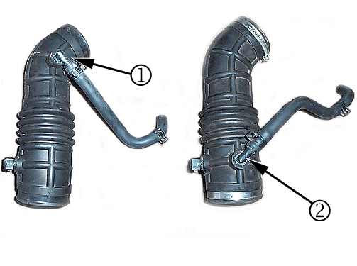
Important: Vehicles produced before December 2004 contain the first design air cleaner assembly and will require the removal of the existing air cleaner outlet duct and breather hose; and the installation of the second design air cleaner outlet duct, P/N96439858, and the second design breather hose, P/N96437830 from Kit 2 . Vehicles produced during and after December 2004 contain the second design air cleaner assembly and will not require installation of the new air cleaner outlet duct and breather hose. Please use Kit 1 on these later vehicles and reuse the existing air cleaner outlet duct and breather hose. Refer to VIN breakpoint information in this bulletin. After this repair is complete all air cleaner outlet ducts should look like design (2).
Service Procedure
Caution: Read all of the information provided in this service procedure carefully before installing the PCV Kit. Failure to install the PCV Kit as outlined in the service procedure may result in personal injury and/or part damage.
The revised PCV system and hose routings are designed to ensure that the PCV lines stay warm and that the PCV is routed further away from the throttle body. Doing so will prevent ice buildup and the potential for throttle freezing in extreme cold temperatures. It is CRITICAL that all hose routings (especially where two hoses are to be in contact to enable the transfer of heat), tie straps, and insulation be installed exactly as described in the procedure. Failure to do so could cause the procedure to be ineffective and thus cause risk to our customers. When Recall 05521 was performed, in many cases, technicians did not route the coolant outlet hose underneath the PCV, did not tie-strap the coolant return line to the PCV, and did not properly install the insulation to the crankcase ventilation tube.| • | Ensure that the insulation is installed as outlined in the service procedure. (Refer to steps 14.1 through 14.3.) |
| • | Ensure that the coolant recovery hose is routed as outlined in the service procedure. (Refer to illustration before step 14.8.) |
| • | Ensure that the tie strap is installed at the PCV valve. (Refer to step 14.10.) |
| • | Refer to this bulletin any time service work is performed on the throttle body, PCV system, or coolant hoses to ensure the PCV system and coolant hoses are installed and routed correctly. |
Caution: Before servicing any electrical component, the ignition key must be in the OFF or LOCK position and all electrical loads must be OFF, unless instructed otherwise in these procedures. If a tool or equipment could easily come in contact with a live exposed electrical terminal, also disconnect the negative battery cable. Failure to follow these precautions may cause personal injury and/or damage to the vehicle or its components.
Important: Determine if the recall was performed on the vehicle. If the recall has been performed, do not discard the crankcase ventilation hose or the coolant outlet hose. Order tie straps and insulation and complete the service procedure as written. If the recall has NOT been performed, order the Kit 1 or Kit 2 and complete the service procedure as written. Ensure that the service manager or a designated inspection person verifies that steps 14.1-14.10 have been completed correctly. Print or copy the 2-page Inspection Checklist for Safety Recall 06515 from this bulletin for each repair. Attach a copy of the signed inspection checklist to the repair order.
An online video of service procedure steps 14.0-14.10 is available for your viewing at: http://service.gm.com/index_en-CA/si.html (preferred Canada English dealer URL) http://service.gm.com/index_fr-CA/si.html (preferred Canada French dealer URL) http://service.gm.com/index_en-US/si.html (preferred US dealer URL)Important: Compare the vehicle air cleaner outlet duct with the first and second designs on page 3 and 12 of this bulletin to determine what kit is required to complete the repair.
- Disconnect the negative battery cable.
- Remove the air cleaner intake duct.
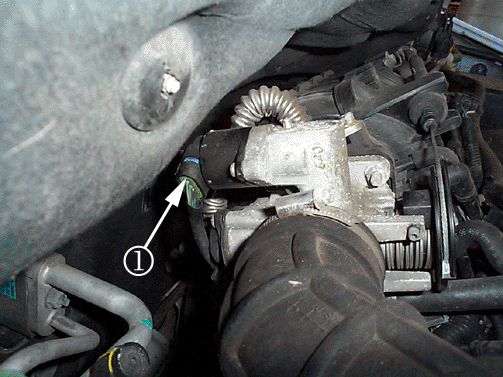
- Disconnect the idle air control (IAC) valve connector (1).
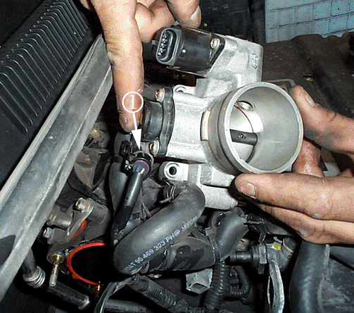
- Disconnect the throttle position (TP) sensor connector (1).
- Remove the air cleaner outlet duct from the throttle body.
- Disconnect the throttle cables (1) by opening the throttle and moving the cable through the release slot.
- Disconnect the vacuum hoses from the throttle body.
- Remove the coolant inlet/outlet hose from the backside of the throttle body.
- Remove the crankcase ventilation hose from the throttle body. If recall 05521 was not performed, discard the crankcase ventilation hose. If recall 05521 was performed, do NOT discard the crankcase ventilation hose.
- Remove the coolant outlet hose and ABS test connector (if equipped) from the coolant surge tank and the side of the throttle body. If recall 05521 was not performed, discard the coolant outlet hose. If recall 05521 was performed, do NOT discard the coolant outlet hose.
- Remove the throttle body retaining nuts.
- Remove the throttle body and discard the gasket. Put the throttle body on a workbench.
- Clean the gasket mating surface on the intake manifold.
- Install A2-PCV T/Body hose assembly. If recall 05521 was not performed, remove the A2-PCV T/Body hose assembly, P/N 96469943, from the kit box and proceed to step 14.1. If recall 05521 was performed, the A2-PCV T/Body hose assembly should be installed on the rear of the throttle body. Remove the A2-PCV T/Body hose assembly from the rear of throttle body and proceed to step 14.1.
- Install the IAC valve connector (1).
- Install the TPS connector (1).
- Connect the vacuum hoses to the throttle body.
- Connect the throttle body cables (1).
- Install the air cleaner outlet duct to the throttle body.
- Install the air cleaner outlet duct (3). Reuse the old screw band on the second design air cleaner duct.
- Connect the electrical connector to the intake air temperature (IAT) sensor (1).
- Install the breather hose (2) to air cleaner duct.
- Replace the oil filler cap with the new oil filler cap, P/N 96469205 (from the kit).
- Connect the negative battery cable.
- Add required engine coolant to the coolant system, P/N 993088, (12378560-US), or equivalent. Refer to SI document 1298421.
- Refer to the Inspection Checklist for Safety Recall Bulletin 06515 on the next two pages. This checklist should be completed by the Service Manager or a designated inspection person after the technician has completed the repair. Copy and attach this document to the RO hard copy, if you have a hybrid or document repair order system; or to the "Customer authorization" copy, if you have an electronic repair order system
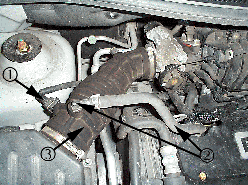
| 2.1. | Disconnect the electrical connector from the intake air temperature (IAT) sensor (1). |
| 2.2. | Disconnect the breather tube (2) from the crankcase ventilation tube. |
| 2.3. | Remove the air cleaner intake duct (3). |
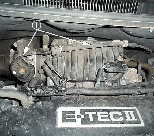
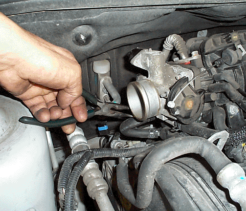
Caution: To avoid being burned, do not remove the radiator cap, surge tank cap or coolant hoses while the engine is hot. The cooling system will release scalding fluid and steam under pressure if radiator cap, surge tank cap or a coolant hose is removed while the engine and radiator are still hot.
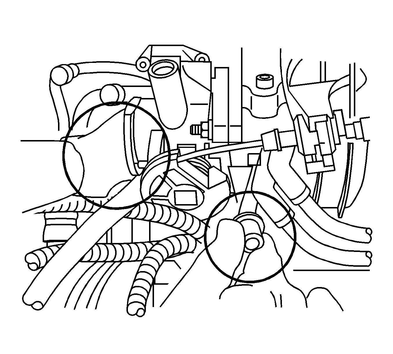
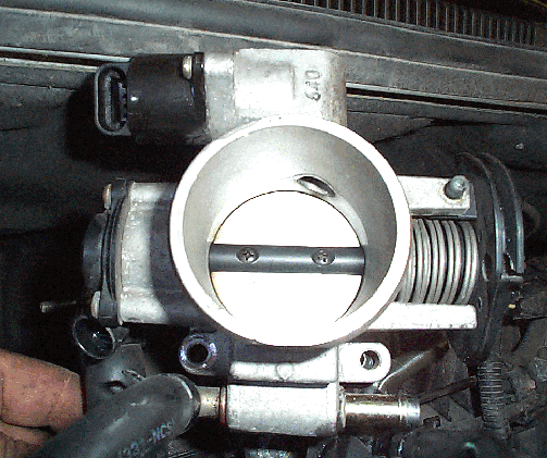
Important: If recall 05521 was performed, the throttle body should be installed to the intake manifold with three nuts and one bolt. Do not discard these fasteners. If recall 05521 was not performed, the throttle body is installed to the intake manifold with four nuts.
Important: Apply Super Lube® multi purpose lubricant, P/N 10953474, or equivalent to the inside ends of the coolant hoses and crankcase ventilation tubes before installing the A2-PCV T/Body hose assembly, P/N 96469943 (from the kit). Perform steps 14-14.3 on a workbench.
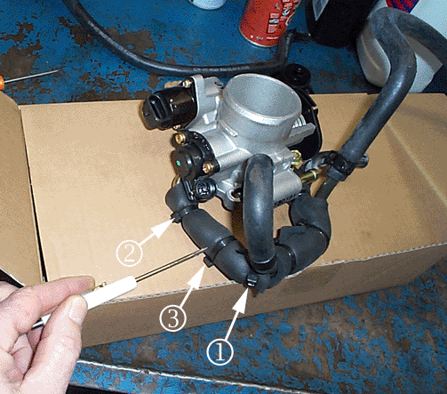
| 14.1. | Tie wrap the protective material, P/N 96469944, around the backside of the throttle body portion of the crankcase ventilation tube of the A2-PCV T/Body hose assembly, as shown in illustration. The length of the protective material should be 10 mm (0.39 in.) longer than the end of the crankcase tube. The tie strap must be located on the curved portion of the A2-PCV T/Body pipe (1). Do not tie wrap the hose above the curved portion of the pipe. Remove excess tie strap. |
| 14.2. | Move the A2-PCV T/Body hose assembly to the rear of the throttle body. |
| 14.3. | Install the backside of the throttle body portion of the new crankcase ventilation tube of the A2-PCV T/Body hose assembly to the pipe on the backside of the throttle body. Insert a second tie strap (2) through the space under the throttle body in order to tie wrap the protective material near the tube opening. Remove excess tie strap. Insert a third tie strap (3) between the first and second tie straps as shown in the illustration. Remove excess tie strap. |
| 14.4. | Install the throttle body assembly with a new gasket to the intake manifold. |
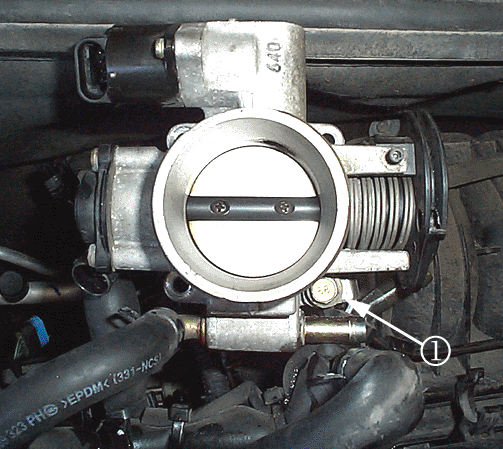
| 14.5. | Install the bottom throttle body retaining bolt (1) through the hole of the A2-PCV T/Body hose assembly bracket. If recall 05521 was not performed, use the bolt from Kit 1 or 2, P/N 94500416. If recall 05521 was performed, re-use the bolt that was removed in step 11. |
Tighten
15 N·m(11 lb ft)
| 14.6. | Install the remaining throttle body retaining nuts. |
Tighten
15 N·m(11 lb ft)
| 14.7. | Install the backside portion of the new coolant inlet/outlet hose of the A2-PCV T/Body hose assembly to the throttle body. |
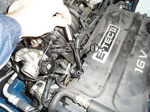
| 14.8. | Install the new coolant outlet hose (1), P/N 96469324 (from the kit), to the coolant surge tank and the side of the throttle body. |
| 14.9. | Install the crankcase ventilation hose to the cam cover and A2-PCV T/Body assembly. |
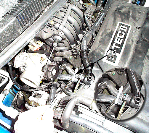
| Notice: Ensure that the tie strap is installed at the PCV valve as shown in illustration. Do not alter or cut the crankcase ventilation hose peak (bend). Verify that the coolant outlet hose is routed underneath the PCV. Once the tie wrap is installed, it is essential to ensure that the coolant hose does not make contact with the throttle cam in order to avoid a potential throttle sticking condition or a coolant leak. Ensure throttle cam and coolant hose do not make contact with throttle cam in the idle position and wide open throttle (WOT) position. |
| 14.10. | Tie wrap (1) the crankcase ventilation hose to the coolant outlet hose, P/N96469324 (from the kit). |
| 14.11. | Install and tie wrap the anti-lock brake system (ABS) test connector on vehicles equipped with ABS. |
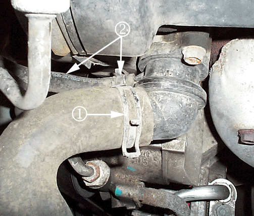
| Caution: To avoid being burned, do not remove the radiator cap, surge tank cap or coolant hoses while the engine is hot. The cooling system will release scalding fluid and steam under pressure if radiator cap, surge tank cap or a coolant hose is removed while the engine and radiator are still hot. |
| 14.12. | Disconnect the radiator upper hose (1) at the side of the thermostat. |

| 14.13. | Disconnect the coolant inlet hose (2) to the thermostat. Discard the coolant inlet hose. |
| 14.14. | Connect the new coolant inlet hose of the A2-PCV T/Body hose assembly to the thermostat. |
| 14.15. | Connect the radiator upper hose. |


Important: Make sure the throttle control cables do not hold the throttle open. With the engine off, check to see that the accelerator pedal is free.
First Design (1) and Second Design (2) Air Cleaner Outlet Duct and Breather Hose.

Important: Vehicles produced before December 2004 contain the first design air cleaner assembly and will require the removal of the existing air cleaner outlet duct and breather hose; and the installation of the second design air cleaner outlet duct, P/N96439858, and the second design breather hose, P/N96437830 from Kit 2 . Vehicles produced during and after December 2004 contain the second design air cleaner assembly and will not require installation of the new air cleaner outlet duct and breather hose. Please use Kit 1 on these later vehicles and reuse the existing air cleaner outlet duct and breather hose. Refer to VIN breakpoint information in this bulletin.

Inspection Checklist for Safety Recall Bulletin 06515
The purpose of this inspection checklist is to ensure that the critical steps in Safety Recall bulletin 06515 have been performed correctly.
Caution: Failure to install the PCV Kit as outlined in the service procedure may result in personal injury and/or part damage.
The revised PCV system and hose routings are designed to ensure that the PCV lines stay warm and that the PCV is routed further away from the throttle body. Doing so will prevent ice buildup and the potential for throttle freezing in extreme cold temperatures. It is CRITICAL that all hose routings (especially where two hoses are to be in contact to enable the transfer of heat), tie straps, and insulation be installed exactly as described in the procedure. Failure to do so could cause the procedure to be ineffective and thus cause risk to our customers. When Recall 05521 was performed, in many cases, technicians did not route the coolant outlet hose underneath the PCV, did not tie-strap the coolant return line to the PCV, and did not properly install the insulation to the crankcase ventilation tube.
Circle Yes or No for each inspection point question. If any inspection point is circled "No", return the vehicle to the technician for repair correction.
- The service manager or designated inspection person has viewed the product Safety Recall 06515 Service Procedure Video. Yes No
- The A2-PCV T/Body hose assembly has been correctly installed to the throttle body.
- The protective material has been properly sized and installed to the crankcase ventilation tube portion of the A2-PCV T/Body hose assembly. There are three tie straps holding the protective material on the crankcase ventilation tube. One tie strap should be located on the curved portion of the A2-PCV T/Body pipe (1). The tie strap at this location is not fastened above the curved portion of the pipe. Excess tie strap at this location has been removed. A second tie strap should be fastened near the crank case ventilation tube opening located on the throttle body (2). Excess tie strap at this location has been removed. A third tie strap (3) should be located between the first and second tie straps as shown in the illustration. Yes No
- A new throttle body gasket was installed. Locate gasket packaging to determine if the gasket was installed. Yes No
- The new bottom throttle body retaining bolt has been installed and the remaining throttle body fasteners have been installed and tightened to 15 N·m(11 lb ft). The A2-PCV T/Body hose assembly is attached to the backside of the throttle body. Yes No
- The new backside coolant inlet/outlet hose of the A2-PCV T/Body hose assembly has been installed to the throttle body. Yes No
- The new coolant outlet hose has been connected to the coolant surge tank and the coolant surge tank side of the throttle body. The hose is routed underneath the PCV. Yes No
Is the new throttle body retaining bolt installed? Is the crankcase ventilation tube installed to the throttle body? Yes No

| 7.1. | The crankcase ventilation hose has been installed to the cam cover and A2-PCV T/Body hose assembly. Yes No |

| Notice: Ensure that the tie strap is installed at the PCV valve as shown in illustration. Do not alter or cut the crankcase ventilation hose peak (bend). Verify that the coolant outlet hose is routed underneath the PCV. Once the tie wrap is installed, it is essential to ensure that the coolant hose does not make contact with the throttle cam in order to avoid a potential throttle sticking condition or a coolant leak. Ensure that the throttle cam and coolant hose do not make contact with the throttle cam in the idle position and wide open throttle (WOT) position. |
| 7.2. | The crankcase ventilation hose has been fastened to the coolant outlet hose with a tie strap. Yes No |
| 7.3. | If required, a tie strap has been installed to the anti-lock brake system (ABS) test connector. Yes No Not Applicable |
The service procedure was performed as written in Safety Recall Bulletin 06515. The service procedure and inspection of the critical steps included in the service procedure were completed on ____________________ (include month, date and year).
Signature of Inspection Person: ____________________________________
Courtesy Transportation
The General Motors Courtesy Transportation Program is intended to minimize customer inconvenience when a vehicle requires a repair that is covered by the New Vehicle Limited Warranty. The availability of courtesy transportation to customers whose vehicles are within the warranty coverage period and involved in a product recall is very important in maintaining customer satisfaction. Dealers are to ensure that these customers understand that shuttle service or some other form of courtesy transportation is available and will be provided at no charge. Dealers should refer to the General Motors Service Policies and Procedures Manual for courtesy transportation guidelines.
Claim Information
Submit a Product Recall Claim with the information indicated below:
Repair Performed | Part Count | Part No. | Parts Allow | CC-FC | Labor Op | Labor Hours | Net Item |
|---|---|---|---|---|---|---|---|
Complete full installation of new PCV kit (includes viewing final inspection video and completing service procedure checklist) | -- | -- | * | MA-96 | V1523 | 1.2 | ** |
Courtesy Transportation for vehicles within the New Vehicle Limited Warranty (US & Canadian GM Dealers) | N/A | N/A | N/A | MA-96 | *** | N/A | **** |
* The "Parts Allowance" should be the sum total of the current GMSPO Dealer net price plus applicable Mark-Up for PCV kit needed to complete the repair. ** The amount identified in the "Net Item" column should represent the actual sum total of the current GMSPO Dealer net price plus applicable Mark-Up for coolant needed to perform the required repairs. *** Submit courtesy transportation using normal labor operations for courtesy transportation as indicated in the GM Service Policies and Procedures Manual for vehicles within the New Vehicle Limited Warranty. **** The amount identified in the "Net Item" column should represent the actual dollar amount for courtesy transportation. | |||||||
Refer to the General Motors WINS Claims Processing Manual for details on Product Recall Claim Submission.
Customer Notification - For Canada
General Motors will notify customers of this recall on their vehicle (see copy of customer letter included with this bulletin).
Dealer Recall Responsibility - All
All unsold new vehicles in dealers' possession and subject to this recall must be held and inspected/repaired per the service procedure of this recall bulletin before customers take possession of these vehicles.
Dealers are to service all vehicles subject to this recall at no charge to customers, regardless of mileage, age of vehicle, or ownership, from this time forward.
Customers who have recently purchased vehicles sold from your vehicle inventory, and for which there is no customer information indicated on the dealer listing, are to be contacted by the dealer. Arrangements are to be made to make the required correction according to the instructions contained in this bulletin. A copy of the customer letter is provided in this bulletin for your use in contacting customers. Recall follow-up cards should not be used for this purpose, since the customer may not as yet have received the notification letter.
In summary, whenever a vehicle subject to this recall enters your vehicle inventory, or is in your dealership for service in the future, you must take the steps necessary to be sure the recall correction has been made before selling or releasing the vehicle.
November 2006Dear General Motors Customer:
General Motors has decided that a defect, which relates to motor vehicle safety, exists in all 2004 - 2005 Chevrolet Aveo and 2005 Pontiac Wave model vehicles, equipped with a 1.6L 4-cylinder engine. As a result, GM is conducting a safety recall.
Some of these vehicles have a condition in which the engine throttle may stick open due to throttle body icing in temperatures near or below -20 degrees Celsius in high humidity environments after an initial cold engine start or while driving. If the engine throttle sticks open while the vehicle is moving, a crash could result without prior warning.
You may have received an earlier safety recall letter for this condition and may have had the repairs performed at your GM dealership. A review of the vehicles repaired, determined that the repairs may not have been effective to prevent the throttle icing condition. Therefore, we are asking you to schedule another appointment at your GM dealership to correct this condition. If the earlier recall was not completed on your vehicle, you should schedule an appointment at your GM dealership to complete this repair at no charge.
You may be contacted by a dealer other than the dealer who sold or is currently servicing your vehicle. Please be advised that you may take your vehicle to the General Motors dealership of your choice to have the recall service work completed.
This letter identifies your vehicle. Presentation of this letter to your dealer will assist their Service personnel in completing the necessary correction to your vehicle in the shortest possible time.
We are sorry to cause you this inconvenience; however, we have taken this action in the interest of your safety and continued satisfaction with our products.
Customer Support Department
General Motors of Canada Limited
06515
