
| Subject: | L91 Short Drive Cycle, Below Freezing Temperatures and High Humidity May Result InThrottle Body Icing Condition (Diagnosis and Report Concern First, Install PCV Valve Kit ) |
| Models: | 2004-2005 Chevrolet Aveo (U.S. Only) |
| with 1.6L 4-Cylinder Engine (VIN 6 -- RPO L91) |
Condition
Important: This bulletin applies to vehicles sold and registered in theU.S. ONLY
. Vehicles sold and registered in Canada should refer to Product Safety Recall 07047.
This condition is possible in 2004 - 2005 Chevrolet Aveo vehicles, equipped with a 1.6L 4-cylinder (RPO L91 - VIN 6) engine and sold in US. A combination of short drive cycle, below freezing temperatures and high humidity might result in an icing condition
that could prevent the engine from starting, cause the engine to stall after initial start or result in a high idle.
Correction
Follow SI procedures for the specific DTC and customer concern to accurately diagnose the condition. Do Not assume a no start or start/stall concern is related to this condition without visible throttle ice evidence or conclusive diagnostics. Work with
the customer to complete the diagnostic check list and consult PQC for a Labor Operation Authorization prior to concluding that a kit installation is necessary. If PQC provides labor authorization then Dealers are to install the new Throttle Body PCV Valve
kit by following the detailed service procedure. TO AVOID WARRANTY CHARGE BACK, DO NOT INSTALL A PCV VALVE KIT WITHOUT A CONCLUSIVE DIAGNOSIS, COMPLETION OF THE DIAGNOSTIC CHECK LIST AND A LABOR AUTHORIZATION FROM PQC.
Diagnostic Survey/Check List - All Questions Must be Answered Prior to Calling PQC For Labor Authorization Request
- What is the customer concern?
| 1.1. | Crank/No Start Condition |
| 1.2. | Start/Stall Condition |
| 1.3. | High Idle Condition After Start |
- How long had the vehicle been parked or running prior to the concern?
| 2.1. | Parked for less than 4 hours |
| 2.2. | Parked for greater than 4 hours |
| 2.3. | While running less than 10 minutes after a cold start |
| 2.4. | While running greater than 10 minutes after a cold start |
- What was the time of day at the time of concern?
AM or PM
- What was the ambient air temperature at the time of the concern?
C°/F°
- What was the weather condition at the time of the concern?
| 5.1. | Snowing - Light/Moderate/Heavy/Blowing Snow |
| 5.2. | Freezing Rain - Light/Moderate/Heavy |
| 5.3. | Foggy - Light/Moderate/Heavy |
| 5.4. | No Precipitation or Fog - Humidity level Low/Med/High |
- What was the date at the time of the concern?
- Where was the vehicle located at the time of the concern?
- What is the normal drive cycle for this customer/vehicle (check all that apply).?
| 8.3. | Delivery Vehicle for business or compensation |
| 8.6. | Normally driven by the same driver |
| 8.8. | Vehicle is often parked for days at a time |
| 8.9. | Normally driven In Town Only |
| 8.10. | Normally driven mostly Highway |
| 8.11. | Normally driven combined Town/Highway |
| 8.12. | Normally driven off road or on unpaved roads |
| 8.13. | Normal Commute Distance One Way (miles) <5, <10, <15, <30, >30 |
| 8.14. | Normal Commute Time One Way (minutes) <5, <10, <15, <30, >30 |
- How did the vehicle arrive at the dealership?
| 9.1. | Driven to repair facility |
| 9.2. | Flatbed or Towed to repair facility |
- Was the customer concern duplicated at the repair facility?
| 10.1. | Yes - Describe Observations and Conditions |
| 10.2. | Are Photos Available? |
| 10.3. | No, Customer concern could not be duplicated |
- Does the vehicle have any Stored DTCs or Check Engine Light?
| 11.1. | Check Engine Light Off |
| 11.3. | Check Engine Light On |
- After completing this diagnostic survey and any SI diagnostics related to the customer concern or stored DTCs, does the technician conclude that Throttle Ice is the cause of the customer concern?
| 12.1. | Yes, Contact PQC to report survey results and seek labor authorization |
| 12.2. | No, Continue to diagnose customer concern. DO NOT INSTALL PCV VALVE KIT
|
| 12.3. | Unsure, Contact TAC |
Service Procedure
Follow SI procedures for the specific customer concern to accurately diagnose the condition. DO NOT assume a no start or start/stall concern is related to this condition without visible throttle ice evidence or conclusive SI diagnostics. Consult PQC prior
to concluding that kit installation is necessary. If a kit is necessary, dealers are to install the new Throttle Body PCV Valve kit by following the detailed service procedure below.
Important: Special Tool EN-48981 Reamer and the Brass Sleeve are required for this procedure. This tool is available from SPX- Kent Moore (1-800-GM-TOOLS).
Important: Before starting, please watch the Service Procedure Video on the GM Service and Parts Operations website. Read all of the information provided in this service procedure carefully before installing the PCV Kit. Failure
to install the PCV Kit as outlined in the service procedure may result in personal injury and/or part damage.
Important: The Inspection Checklist at the end of this Service Procedure is necessary to ensure that the critical steps in this bulletin have been performed correctly.
Important: If the vehicle was towed in due to throttle body icing, the vehicle will have to be thawed out. The engine will need to run at idle for two hours before shutting off the engine. Then the engine oil and filter will have
to be changed before starting this service procedure.
PCV Valve Kit P/N 96892259 Components
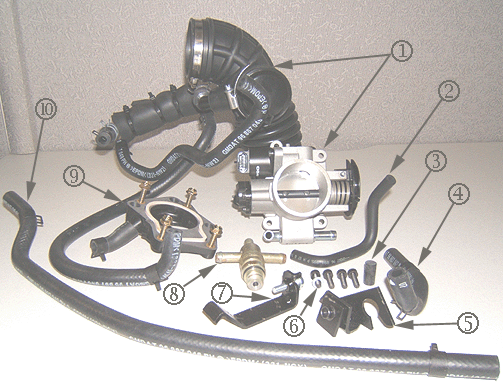
- Throttle Body Assembly P/N 96889775
| - | Breather Assembly P/N 96892215 includes: |
| - | Air Outlet Hose P/N 96889507 |
| - | Coolant Inlet Hose to Throttle Body P/N 96887049 |
| - | Coolant Inlet Hose to Thermostat Housing P/N 96887048 |
- MAP Sensor Vacuum Hose P/N 96891995
- Intake Manifold Vacuum Plug P/N 96351328
- Throttle Body Inlet Hose P/N 96887047
- Accelerator Cable Bracket Assembly P/N 96875545
- Throttle Body Adapter to Intake Manifold Bolt/Screw P/N 94500751 (4) includes:
-- Copper Washer P/N 96892557
- MAP Sensor Bracket Assembly P/N 96891920; Screw P/N 94500414
- PCV Valve P/N 96892257
- Throttle Body Adapter P/N 96875543; includes:
| - | PCV Valve Hose P/N 96892258 |
| - | Throttle Body to Adapter Bolts/Screws P/N 94500411 (4) |
- Throttle Body to Coolant Outlet Hose P/N 96887046
Not Shown -- Tie Strap P/N 96224564
Crankcase Breather Tube Insulation P/N 96941983 Components

- Worm Type Clamp P/N 94530121
- Crankcase Breather Tube Insulation P/N 96941983
- Spring Type Clip Clamp P/N 94530682
PCV Valve Kit Installation
- Some MY2004 vehicles may have a radio security code. Refer to Corporate Bulletin Number 04-00-89-007. Record radio station presets for reprogramming at the end of this procedure.
Caution: Unless directed otherwise, the ignition and start switch must be in the OFF or LOCK position, and all electrical loads must be OFF before servicing any electrical component. Disconnect the negative battery cable to
prevent an electrical spark should a tool or equipment come in contact with an exposed electrical terminal. Failure to follow these precautions may result in personal injury and/or damage to the vehicle or its components.
- Disconnect the
negative battery cable.
Caution: To avoid being burned, do not remove the radiator cap or surge tank cap while the engine is hot. The cooling system will release scalding fluid and steam under pressure if radiator cap or surge tank cap is removed while
the engine and radiator are still hot.
- Remove the coolant surge tank cap and engine oil filler cap in order to remove inner pressure.
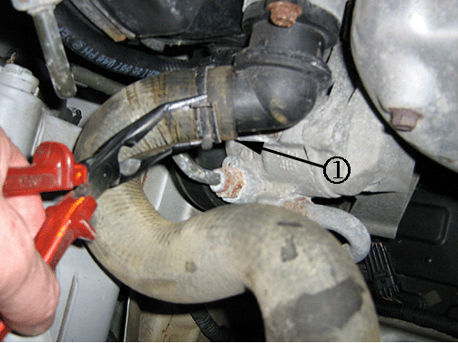
- Drain the coolant by separating the upper radiator hose from the thermostat housing (1).
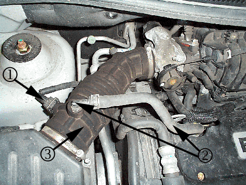
- Remove the clamp from the air cleaner outlet duct at the throttle body.
| 5.1. | Disconnect the electrical connector from the intake air temperature (IAT) sensor (1). |
| 5.2. | Disconnect the breather tube (2) from the crankcase ventilation tube |
| 5.3. | Remove clamp from the air cleaner outlet duct at air cleaner and remove the intake duct (3). |
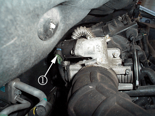
- Disconnect the idle air control (IAC) valve connector (1).
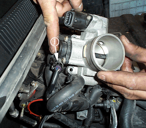
- Disconnect the throttle position (TP) sensor connector (1).
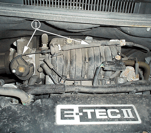
- Disconnect the throttle cable(s) (1) by opening the throttle and moving the cable through the release slot. Refer to the Throttle Body Cable Removal, Installation and Adjustment Procedure later in this bulletin.
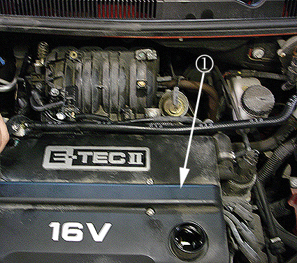
- Remove the engine cover (1). Refer to Engine Cover Replacement in SI.
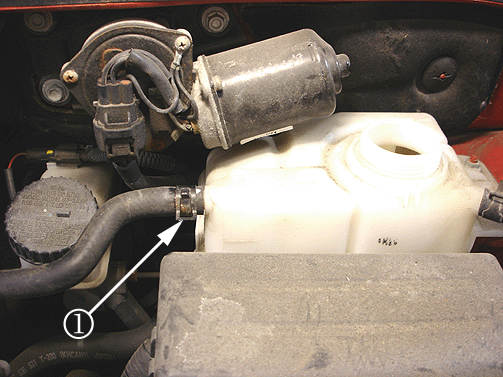
- Disconnect the coolant return hose (1) from the surge tank.
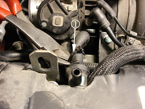
- Remove the nylon strap (1) which holds the PCV valve to the coolant return hose. Separate the PCV hose from the PCV valve and remove the coolant return hose from the throttle body.
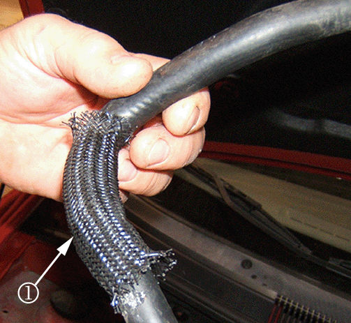
- Remove the old coolant return hose and retain the protective webbing sleeve (1) for use later in the procedure. Unstrap the ABS test connector (if equipped) from the coolant surge tank side.
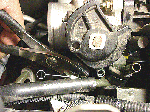
- Remove the coolant inlet hose from the throttle body (1) and pull away from the throttle body and from the top of the timing cover. The other end will be removed later.
- Remove the throttle body. (Retain nuts for Step 16.)
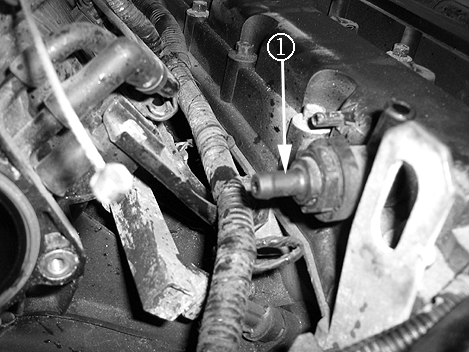
- Unscrew the old PCV valve (1) from the cam cover and discard.
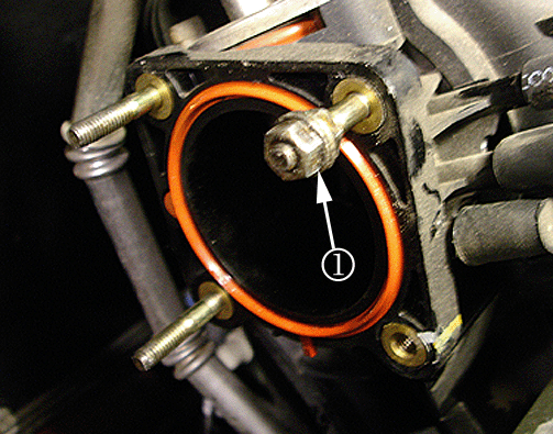
- Install the old throttle body nuts (1) to a stud bolt and tighten/jam both nuts together.
Once the nuts are jammed together, turn counterclockwise to remove the stud bolt (1). Repeat the process for the other stud
bolts then discard all three stud bolts.
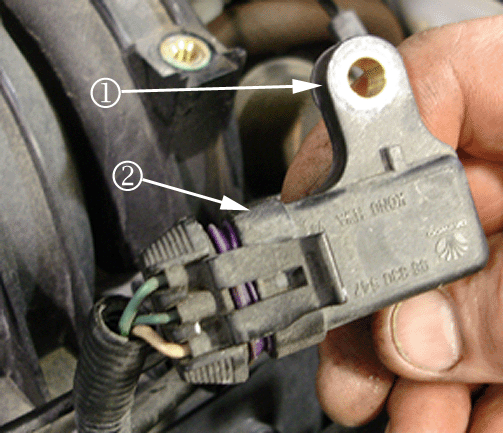
- Disconnect and remove the MAP sensor (1) from the intake manifold.
| 17.1. | Disconnect the MAP sensor wiring harness connector (2). |
| 17.2. | Save the old MAP sensor (1). The MAP sensor will be reinstalled to a new location later in this service procedure. |
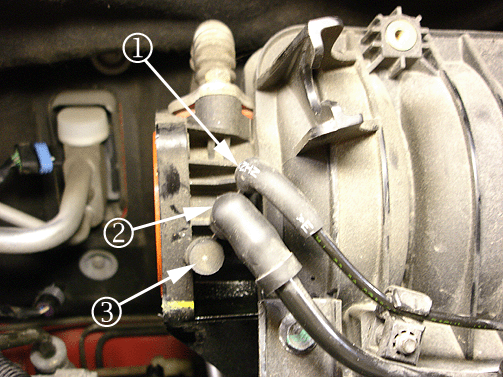
- Remove the MAP sensor vacuum hose (1), EVAP canister purge solenoid vacuum hose (2) and rubber plug (3) from the intake manifold. Discard the hose (1) and rubber plug (3).
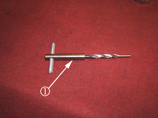
Notice: Extreme care must be taken not to damage the intake manifold port when using the reamer tool.
Important: Special Tool EN-48981 Reamer and the Brass Sleeve are required for this procedure. This tool is available from SPX- Kent Moore (1-800-GM-TOOLS).
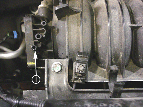
Important: Take your time reaming the port and do not push down hard or force the tool through the port. Excess force could result in cracking the intake manifold port during the reaming operation.
- Use GM Special Tool EN-48981 Reamer and Brass Sleeve Tool to enlarge the lower port of the intake manifold from 4mm to 6mm (1).
Prior to starting the reaming procedure on the intake manifold port, ensure that the intake manifold is at shop
temperature.
- Insert a clean rag inside the intake manifold throttle body bore to prevent any debris and burrs from falling inside the intake manifold.
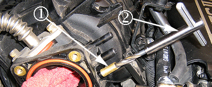
- Place the brass sleeve tool over the lower intake manifold port (1) and press down to seat. This will prevent the port from cracking during the reaming operation. Before starting, refer to the following tips on using the reamer with brass sleeve.
| | Important: Lubricating the reamer tool with windshield washer fluid may ease the cutting process.
|
| 21.1. | Lubricate the reamer tool EN-48981 (2) with windshield washer fluid then insert and turn the tool clockwise while applying a very slight downward pressure and slowly work the tool back and forth as required. |
| 21.2. | Remove the tool (2) while exerting a slight upwards motion while maintaining a clockwise rotation. While working the tool out, hold the brass sleeve (1) in place to prevent losing it. Clean the tool and lubricate it with windshield washer fluid
then re-insert the tool in the port and continue reaming. Repeat as required. |
| 21.3. | Once the tool (2) has bottomed out, continue turning the tool in a clockwise rotation while exerting a slight upwards motion to release the reamer. |
| 21.4. | Remove the brass sleeve from the port (1). |
Important: Retain Special Tool EN-48981 Reamer and the Brass Sleeve for the next vehicle.
Important: If the intake manifold requires replacing due to damage caused by the reaming process (1), the new intake manifold MAP sensor vacuum port may also require reaming to 6mm using the reaming operation outlined in this bulletin.
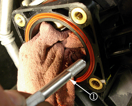
- Using a utility knife or equivalent, carefully remove any burrs from the inside of the intake manifold throttle body bore (1). Remove the rag and ensure that the bore is free of debris.
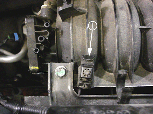
- Remove and discard the stud bolt closest to the throttle body from the intake manifold (1) and save the plastic retainer. Refer to Step 16 in this bulletin for the removal of the stud bolt.
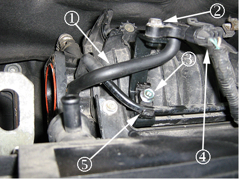
- Install the new MAP sensor bracket (P/N 96891920), old retainer (5) and new bolt/screw (3) (P/N 94500414). Ensure that the larger slot of the retainer is at the bottom when installed as shown above (5).
Tighten
Tighten the MAP sensor bracket bolt/screw (3) to 10-12 N·m(90 lb in).
- Install the Evap hose to the middle vacuum port on the intake manifold and connect the hose to the retainer as shown above (5).
Important: The MAP sensor hose and bracket position (1) is critical. The hose should not contact the MAP sensor bracket (see above).
- Install the MAP sensor on the new MAP sensor bracket (2) and connect the MAP sensor wiring harness connector. The MAP sensor connector should be oriented at a 5 o’clock position relative to the Intake Manifold with the harness positioned toward the
front of the vehicle as shown above (4).
Tighten
Tighten the MAP sensor bolt/screw (2) to 10-12 N·m(90 lb in).
- Install the MAP sensor vacuum tube assembly (1) (P/N 96891995) (1) between the lower port on the intake manifold to the underside of the MAP sensor. Ensure that the hose is oriented with the paint mark toward the intake manifold. Install the rubber
plug (P/N 96351328) on the remaining open intake manifold port.
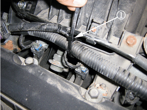
- Secure the MAP sensor engine wire harness to the intake manifold bracket using a nylon tie strap (1). Ensure that the MAP sensor wire harness is not secured too tightly and allow some room for movement. Use nylon tie strap (P/N
96224564).
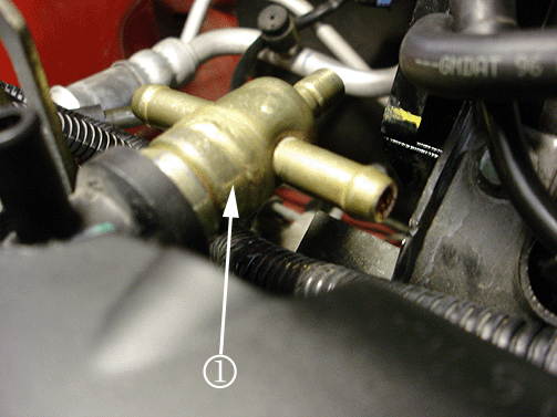
- Apply Teflon tape to the new PCV Valve threads. Install the new PCV valve (1) (P/N 96892257) into the cam cover and ensure that the pipes are in a horizontal plane.
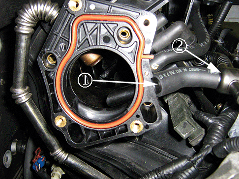
- Install the PCV hose (P/N 96892258) (1) to the throttle body adapter and then install the other end marked with paint facing up to the PCV valve (2).
- Install the throttle body adapter (P/N 96875543).
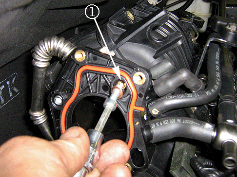
- Install four bolts/screws (P/N 94500751) to secure the throttle body adapter to the intake manifold. Install the copper washer (gasket) (P/N 96892557) (1) provided in the kit under the right upper bolt.
Tighten
Tighten the four throttle body adapter bolts/screws to 10-12 N·m(90 lb in).
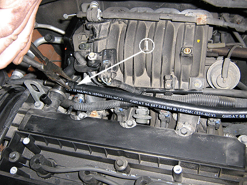
- Install the throttle body hose assembly coolant outlet return hose (1) (P/N 96887046) from the PCV valve, ensuring that the paint mark is facing up and connected toward the PCV valve assembly. Connect the other end to the surge
tank. Re-install the tie strap for the ABS Test Connector (if equipped) to the side of the coolant surge tank.
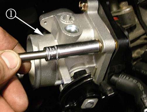
- Install the throttle body assembly (1) (P/N 96889775) on the throttle body adapter using the four throttle body bolts/screws (P/N 94500411).
Tighten
Tighten the four throttle body adapter bolts/screws to 10-12 N·m(90 lb in).
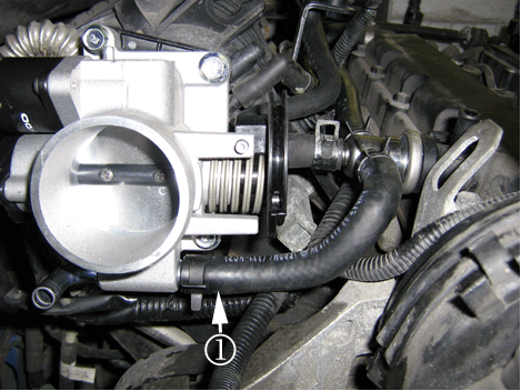
Important: The routing of the throttle body coolant hoses is very critical.
- Connect the throttle body hose assembly short coolant inlet hose (P/N 96887047) to the throttle body (1).
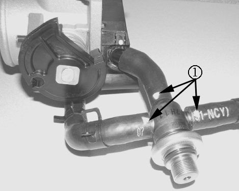
Important: The picture above is for illustration purposes only. The intent is to show the correct routing of the coolant hoses with the paint mark facing upwards and connected at the PCV valve assembly.
- The following coolant hoses must have the white paint marks (1) at the PCV valve assembly.
| - | Throttle Body Adapter to PCV |
| - | Coolant Outlet Return to PCV |
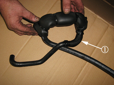
- Install the protective webbing sleeve (1) over the coolant inlet hose (P/N 96887049) close to the foam insulator. (Refer to the P/N on the hose which is part of the breather assembly, P/N 96892215). Install black electrical tape
to the ends of the webbing sleeve in order to keep in the correct position.

- Connect the coolant inlet hose (P/N 96887049) (refer to the P/N on the hose which is part of breather assembly, P/N 96892215) to the rear throttle body port (1).
- Connect the IAC valve and TPS wiring harness connectors to the throttle body assembly.
Ensure both connectors are fully engaged by lightly pulling on them.
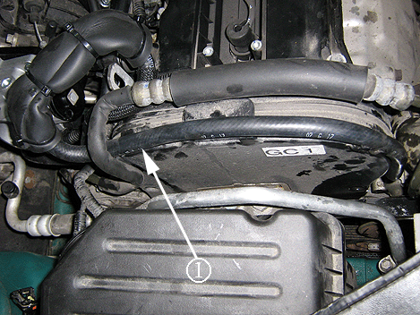
- Position the new coolant inlet hose (1) (P/N 96887048) (refer to the P/N on the hose which is part of breather assembly, P/N 96892215) on top of the timing belt cover in place of the old hose. The new coolant inlet hose should
be positioned under the power steering pipe.
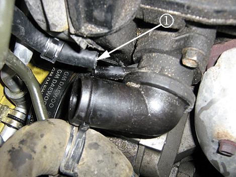
- Remove and discard the old coolant inlet hose from the thermostat housing and connect the new coolant inlet hose (1). Use long-nose pliers to remove and install the spring clamp.

- install the upper radiator hose to the thermostat housing (1).
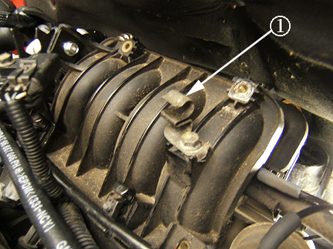
- Remove the upper intake manifold accelerator cable clamp from the intake manifold and move it to the old MAP sensor location (1).
- Install the accelerator cable clamp 180 degrees from the original position as shown (1) and tighten the bolt.
Tighten
Tighten the accelerator cable clamp bolt to 10-12 N·m(90 lb in).
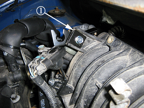
- Install the new accelerator cable bracket (P/N 96875545) as shown to the intake manifold. Ensure that the bracket retaining plate is positioned as shown (1) with the rounded corner oriented upwards and the depression oriented
toward the bolt head.
The retaining plate should not protrude beyond the intake mounting tab. This is critical for proper throttle cable alignment and operation.
Tighten
Tighten the accelerator cable bracket bolt to 10-12 N·m(90 lb in).
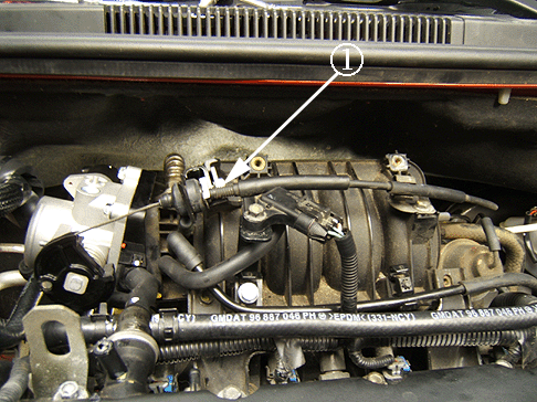
- Install the accelerator cable to the newly positioned intake manifold bracket/clamp and then to the throttle body. If equipped, install the cruise control cable. Check for correct throttle opening and closing positions by operating
the accelerator pedal.
Make sure that the throttle valve reaches wide open throttle position (1). If it does not, inspect for coolant hose spring clip contact with the throttle body accelerator cable cam.
- Adjust the throttle cable. Refer to the Throttle Cable Adjustment Service Procedure later in this Bulletin.
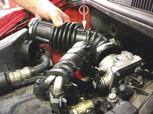
- Install the new Air Cleaner Outlet Duct (1) (P/N 96889507) between the throttle body and air cleaner assembly and tighten the clamps.
Install the IAT sensor connector. Ensure proper connection by lightly pulling
on the connector.
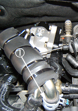
- Connect the breather assembly hose (P/N 96892215) to the PCV valve and to the new air cleaner outlet duct. Secure the hose to the base of the PCV valve (1) on the cam cover and attach it with a spring clamp.
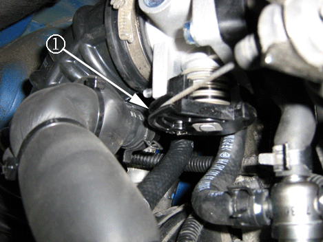
- Check for the correct throttle opening and closing positions by operating the accelerator pedal. Make sure that the throttle valve reaches wide open throttle position (1). If it does not, inspect for the following:
Coolant hose spring clip contact with the throttle body accelerator cable cam.
- Remove the EGR electrical connector.
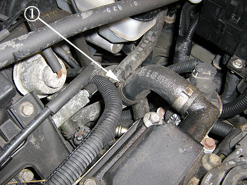
- Remove the lower crankcase external ventilation hose clamp (1).
- Remove the external ventilation hose from the crankcase pipe and fold the hose away from the pipe.
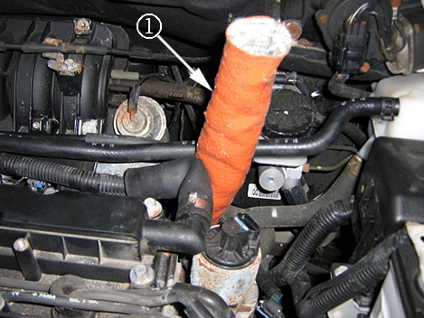
Important: When handling the fiberglass crankcase breather tube insulation sleeve, wear gloves.
- Install the crankcase breather tube insulator sleeve (P/N 96941983) (1) over the external ventilation pipe assembly while working out any wrinkles and pushing the insulator down completely toward the engine crankcase.
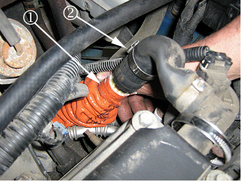
- Push the crankcase breather tube insulator sleeve down far enough to expose the top two inches of the crankcase vent pipe. Install the spring clip (ear type) clamp (P/N 94530682) over the vent hose and install the rubber vent
hose over the vent pipe and then crimp the spring clamp on to the rubber hose (1).
Caution: To avoid any vehicle damage, serious personal injury or death when major components are removed from the vehicle while the vehicle is supported by a hoist, support the vehicle with jack stands at the opposite end the
components are being removed, and strap the vehicle to the hoist.
- Raise the vehicle. Refer to Lifting and Jacking the vehicle in SI.
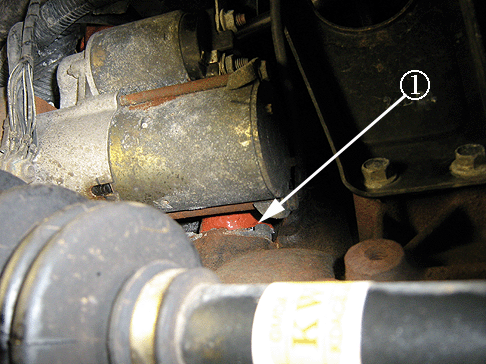
Important: Make sure that the insulator sleeve is bottomed out against the engine block.
- Verify that the insulator sleeve is bottomed out against the engine block (1).
- Lower the vehicle.
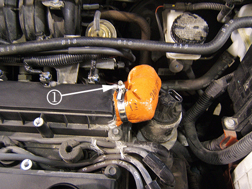
Important: The worm clamp should be installed toward the back of the valve cover with the clamp screw (1) positioned up so that the engine cover will install properly.
- Slide the excess insulator sleeve up over the external ventilation hose as shown.
Open the worm clamp (1) (P/N 94530121). Install and secure the clamp around the external ventilation hose.
- Install the EGR electrical connector.
Important: Install engine oil filler cap (P/N 96469205).
- Install the engine cover, coolant surge tank cap and engine oil filler cap.
- Top off the coolant. Refer to SI for the Cooling System Draining and Filling Procedure.
- Install the battery negative cable.
- Perform the following Idle Relearn Procedure:
| 64.1. | Turn the ignition ON. |
| 64.2. | Turn the ignition OFF for 15 seconds. |
| 64.3. | Turn the ignition ON for 5 seconds. |
| 64.4. | Turn the ignition OFF for 15 seconds. |
| 64.5. | Start the engine in park/neutral. |
| 64.6. | Allow the engine to run until the engine coolant is above 85°C (185°F). |
| 64.7. | Turn the A/C ON for 10 seconds, if equipped. |
| 64.8. | If the vehicle is equipped with an automatic transaxle, apply the parking brake. While pressing the brake pedal, place the transaxle in D (drive) for 10 seconds. |
| 64.9. | Turn the A/C OFF for 10 seconds, if equipped. |
| 64.10. | If the vehicle is equipped with an automatic transaxle, while pressing the brake pedal, place the transaxle in park/neutral. |
| 64.11. | Turn the ignition OFF. The idle learn procedure is now complete. |
- Road test the vehicle with a Tech 2® Scan Tool.
- Reset the clock and radio stations.
Throttle Body Cable Removal, Installation and Adjustment Procedure
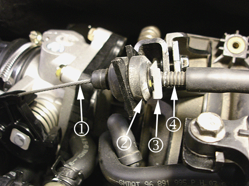
Accelerator Cable Removal Procedure
- Remove retaining clip (3) from throttle cable and pull cable towards grommet (2) loosing the cable (4).
- Depress the throttle body accelerator cam by rotating it to its full open position then remove the accelerator cable (1) and allow the accelerator cam to go back to its full close position.
Accelerator Cable Installation and Adjustment Procedure
Important: Make sure that the throttle control cable does not hold the throttle open. With the engine OFF, check to see that the accelerator pedal is free.
On a properly adjusted throttle cable, the metal cable (1) should be no higher than the top on the cam groove. If the cable is too high or loose remove clip (3) pull back on cable casing (4) away from throttle body until cable (1) at cam is no higher than
the top of the groove.
- Remove retaining clip (3) from throttle body cable and pull cable casing (4) away from throttle body to remove any excess play in the accelerator cable.
- Re-install retaining clip (3) on the throttle body cable (4) and ensure the washer is between the clip and grommet (2).
- Slowly depress the accelerator pedal to the floor two or three times.
- Verify the cable adjustment. Repeat Step 1 as required to ensure the throttle body cam or cable are not binding or contacting any other component.
Bulletin Inspection/Checklist for PCV Valve Kit
The purpose of this inspection checklist is to ensure that the critical steps outlined in the bulletin PCV Valve Kit have been performed correctly. The revised Throttle Body, PCV Valve and Crankcase Ventilation system is designed to ensure that the accumulation
of moisture in the crankcase is kept to a minimum, and any moisture that accumulates is allowed to pass through the PCV system without freezing . Doing so will prevent ice buildup and the potential for throttle freezing in extreme cold temperatures. It is CRITICAL
that the following steps have been performed and installed exactly as described in the bulletin service procedure. Failure to do so could cause the repair procedure to be ineffective. Please verify that the following service procedures have been completed correctly:
Inspection
- MAP Sensor Lower Intake Manifold port was enlarged from 4mm to 6mm with the GM Special Tool EN-48981 reamer and brass sleeve. Refer to Service Procedure Steps 19-22 in this service bulletin.
- Installation of the copper washer (gasket) provided in the kit under the right upper bolt. Refer to Service Procedure Step 32 in this service bulletin.
- The attaching hoses must have the white paint mark at the PCV valve assembly. Refer to Service Procedure Step 36 in this service bulletin.
- Installation of the protective webbing sleeve over the coolant inlet hose close to the foam insulator. Refer to Service Procedure Step 37 in this service bulletin.
- Ensure that the accelerator bracket retaining plate is positioned with the rounded corner oriented upwards and the depression is oriented toward the mounting bolt head. The bracket retaining plate should not protrude beyond the intake manifold mounting
tab. This is critical for proper throttle cable alignment and operation. Refer to Service Procedure Step 45 in this service bulletin.
- Ensure that the insulator sleeve over the external crankcase ventilation pipe assembly to the engine block/crankcase is installed correctly. Refer to Service Procedure Step 54 in this service bulletin.
Parts Information
TO AVOID WARRANTY CHARGE BACK, DO NOT INSTALL A PCV VALVE KIT WITHOUT A CONCLUSIVE DIAGNOSIS, COMPLETION OF THE DIAGNOSTIC CHECK LIST AND A LABOR AUTHORIZATION FROM PQC.
Part Number
| Description
|
96892259
| PCV Valve Kit
|
96941983
| Crankcase Breather Tube Insulation Kit
|
Warranty Information
Important: For claims to be paid, the Bulletin Checklist for PCV Valve Kit must be attached to the repair order.
For vehicles repaired under warranty, use:
Labor Operation
| Description
| Labor Time
|
J7922*
| Complete Installation of New PCV Valve Kit
| 1.2 hrs
|
Add:
| Idle Learn Procedure with A/C
| 0.3 hr
|
Idle Learn Procedure without A/C
| 0.2 hr
|
Change Engine Oil (Only if the Vehicle was Towed in Due to Icing)**
| 0.4 hr
|
* This is a unique labor operation for bulletin use only. It will not be published in the Labor Time Guide.
**For claims to be paid, a copy of tow bill must be attached to the repair order if the engine oil was changed due to icing.
|
Checklist
Circle "Yes" or "No" for each inspection point question. If any inspection point is circled "No", return the vehicle to the technician for repair correction.
- Did the designated inspection person view the Service Procedure Video? Yes -- No
- Was GM Special Tool EN-48981 reamer and brass sleeve used to enlarge the MAP sensor vacuum port at the intake manifold? Yes -- No
- Was the new engine oil filter cap (P/N 96469205) installed? Yes -- No
- Were the MAP sensor, MAP sensor bracket, and vacuum hoses re-located and correctly positioned to the new location on the intake manifold? Yes -- No
- Was the new PCV valve installed with Teflon tape on the threads and installed at a horizontal plane? Yes -- No
- Were the throttle body assembly and all hoses installed correctly? Yes -- No
- Was the accelerator cable bracket relocated to the old MAP sensor bracket location on the intake manifold? Yes -- No
- Was the accelerator cable adjusted per the service information in this bulletin? Yes -- No
- Was the new crankcase breather tube insulator sleeve installed correctly over the external ventilation pipe assembly to the engine block? Yes -- No


