Tools Required
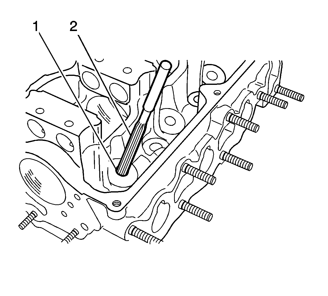
| • | EN 46597 (09916-37320) Vavle Guide Reamer (5 mm or 0.1969 in) |
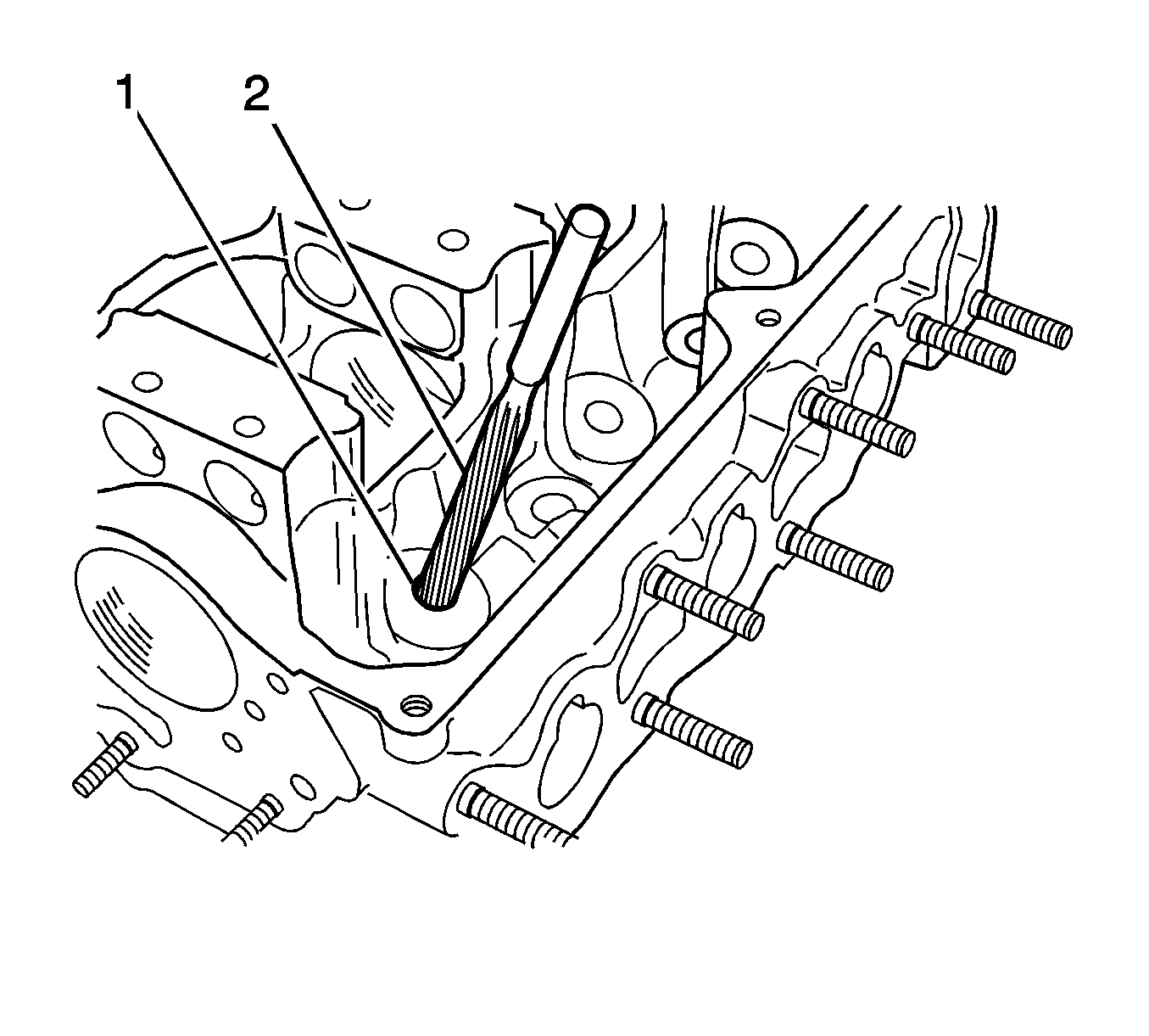
| • | EN 46570 (09916-38210) Valve Guide Reamer (11 mm or 0.4331 in) |
| • | EN 46569 (09916-14510) Valve Spring Compressor |
| • | EN 47518 (09916-48210) Valve Spring Compressor Attachment |
| • | EN 46573 (09917-88220) Valve Guide Installer Attachment |
- Make the valve guide hole using EN 46570 (2). Before installing the new valve guide into the cylinder head, ream the guide hole with the 11 mm reamer to remove burrs. Make sure the guide hole cones to a complete roundness (1).
- Peen and install the new valve guide using the EN 46573 (2).
- Inspect the protruded part of the guide from the cylinder head (a).
- Repair the valve guide bore with the EN 46597 (2).
- Remove any debris from the hole.
- Install the valve spring seats.
- Install the seal to the guide only by pushing the special tool by hand.
- Install the valve stem oil seal to the valve guide. After applying engine oil to the seal and installing the seal to the valve guide, make sure the seal is properly fixed to the valve guide.
- Install the valve (1) to the valve guide.
- Install the valve springs (2) and the spring retainers (1).
- Using the EN 46569 and EN 47518 , compress the valve spring.
- Install the valve keepers.
- Install the camshaft front oil seal from the housing hole.
- Coat the camshaft front oil seal, the cam, and the camshaft journal with the engine oil.
- Install the camshaft front oil seal to the housing hole.
- Install the camshaft to the cylinder head.
- Install the screws with the camshaft thrust plate.
- Coat the rocker arms and the rocker arm shafts with the engine oil.
- Install the rocker arm spring and the rocker arm.
- Install the rocker arm shaft mounting bolts.
- Install the intake manifold studs.
- Install the intake manifold with the gasket.
- Install the intake manifold.
- Install the intake manifold nuts in the sequential order shown.
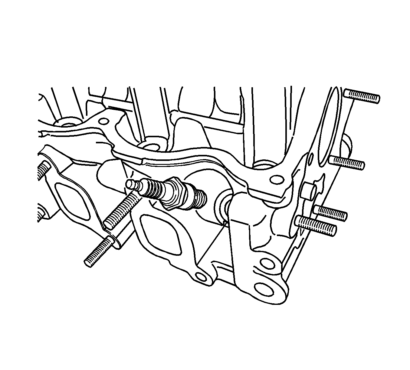
- Install the spark plugs.
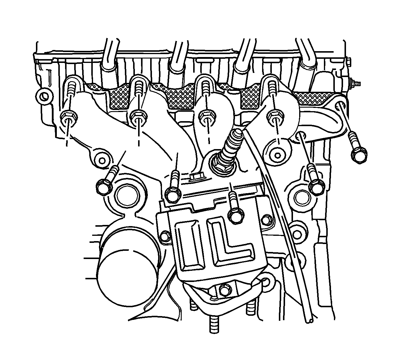
- Install the exhaust manifold gasket and the exhaust manifold.
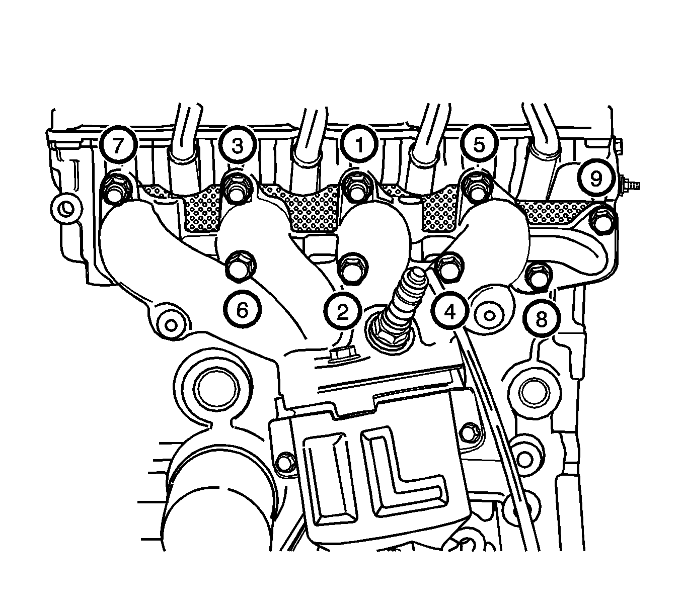
- Install the bolts and nuts in the sequential order shown.
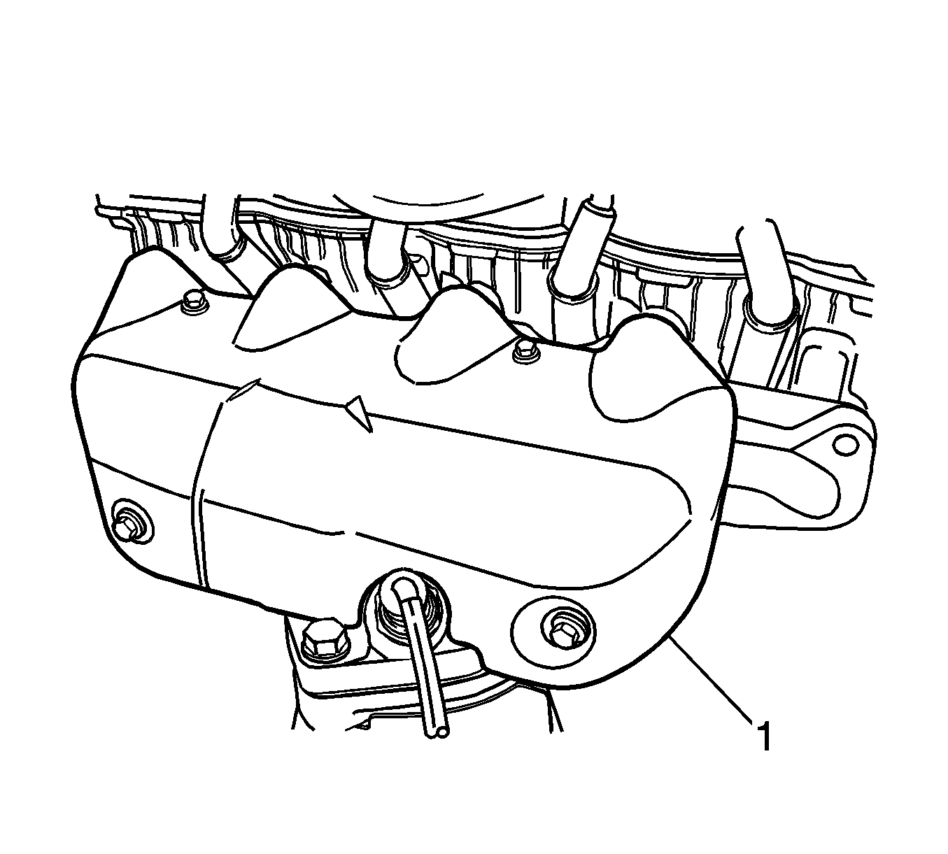
- Install the exhaust manifold heat shield (1).
- Install the exhaust manifold heat shield bolts.
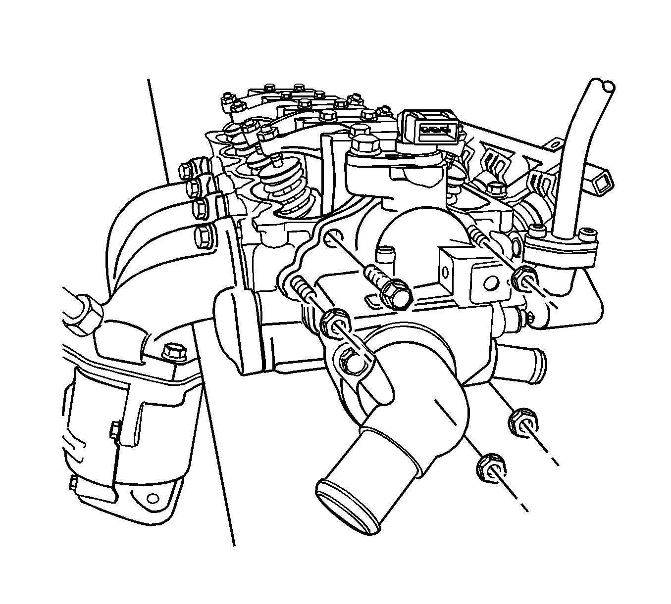
- Install the water outlet case.
- Install the water outlet case mounting bolts.
- Install the cylinder head with the intake manifold and exhaust manifold attached. Refer to Cylinder Head Replacement .
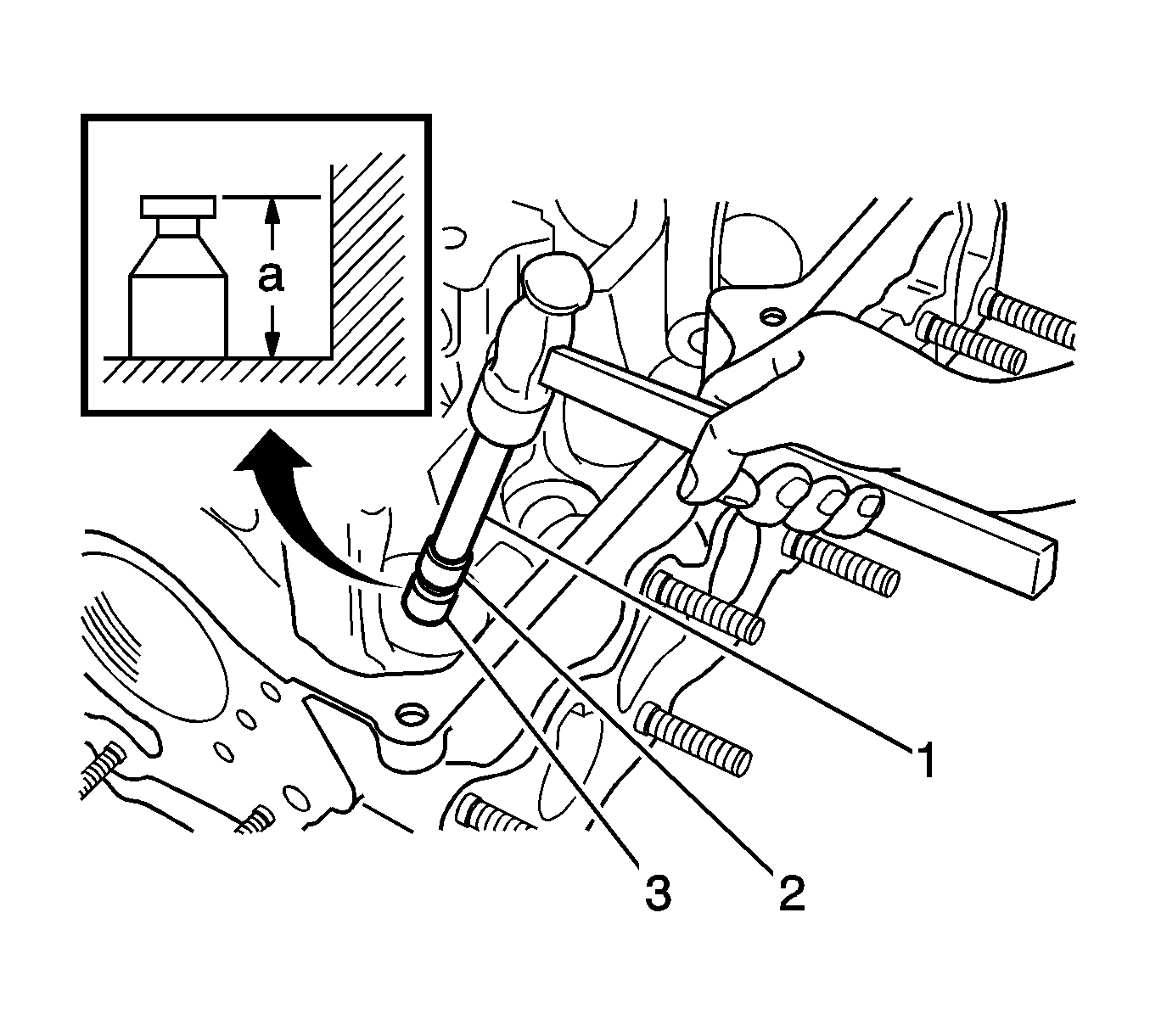
Notice: Heat the cylinder head uniformly at a temperature 80-100°C (176-212°F) in order not to deform the cylinder head. Drive the new valve guide completely into the cylinder head with the valve guide installer.
Important: Once disassembled, do not reuse the valve guide. Replace it with the new oversized valve guide.
Specifications
| • | The valve guide oversize is 0.03 mm (0.0012 in). |
| • | The valve guide protrusion is 14 mm (0.5512 in). |
Specification
The valve guide bore width is 5 mm (0.1969 in).
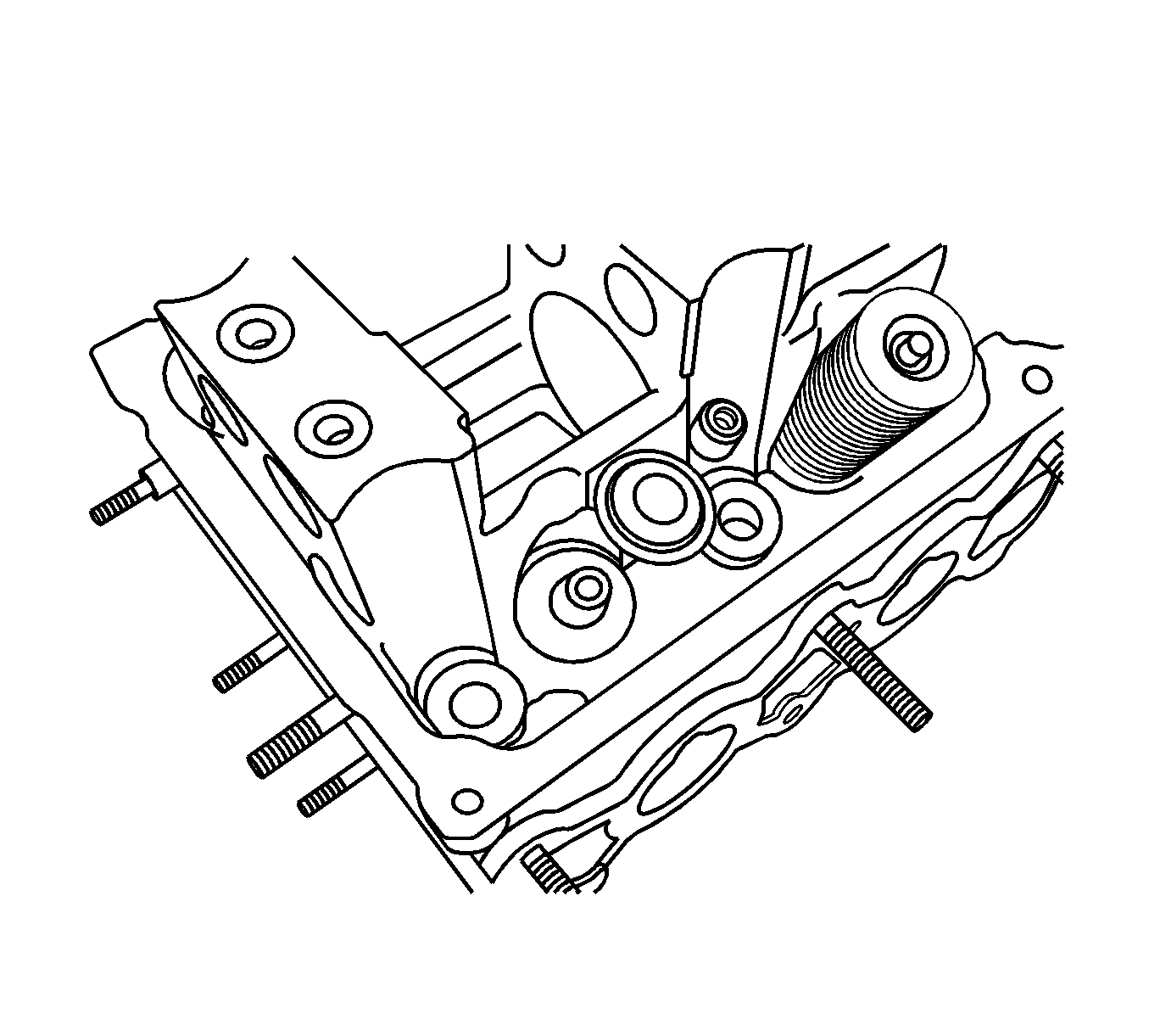
Notice: Tapping or hitting the tool may cause damage to the seal.
Important: Do not reuse the disassembled oil seal. Replace the disassembled oil seal with a new one.
Important: When installing the new oil seal, knee tap or hit the tool with a hammer.
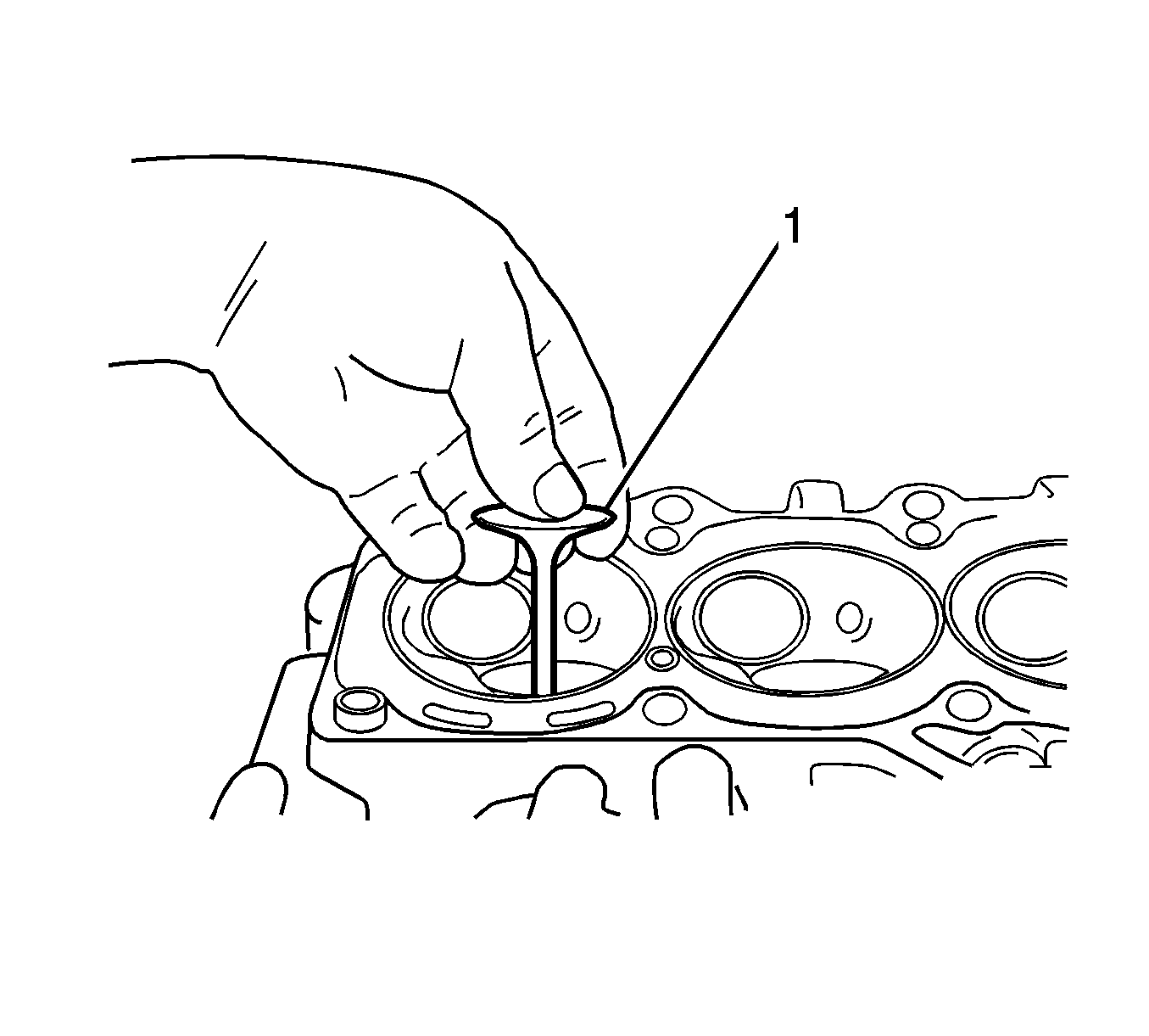
Important: Before installing the valve, coat the stem seal, valve guide, and valve stem with engine oil.
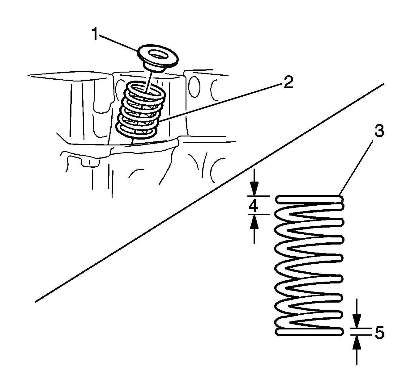
Caution: Valve springs can be tightly compressed. Use care when removing the retainers and plugs. Personal injury could result.
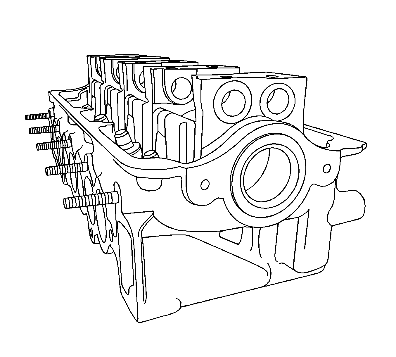
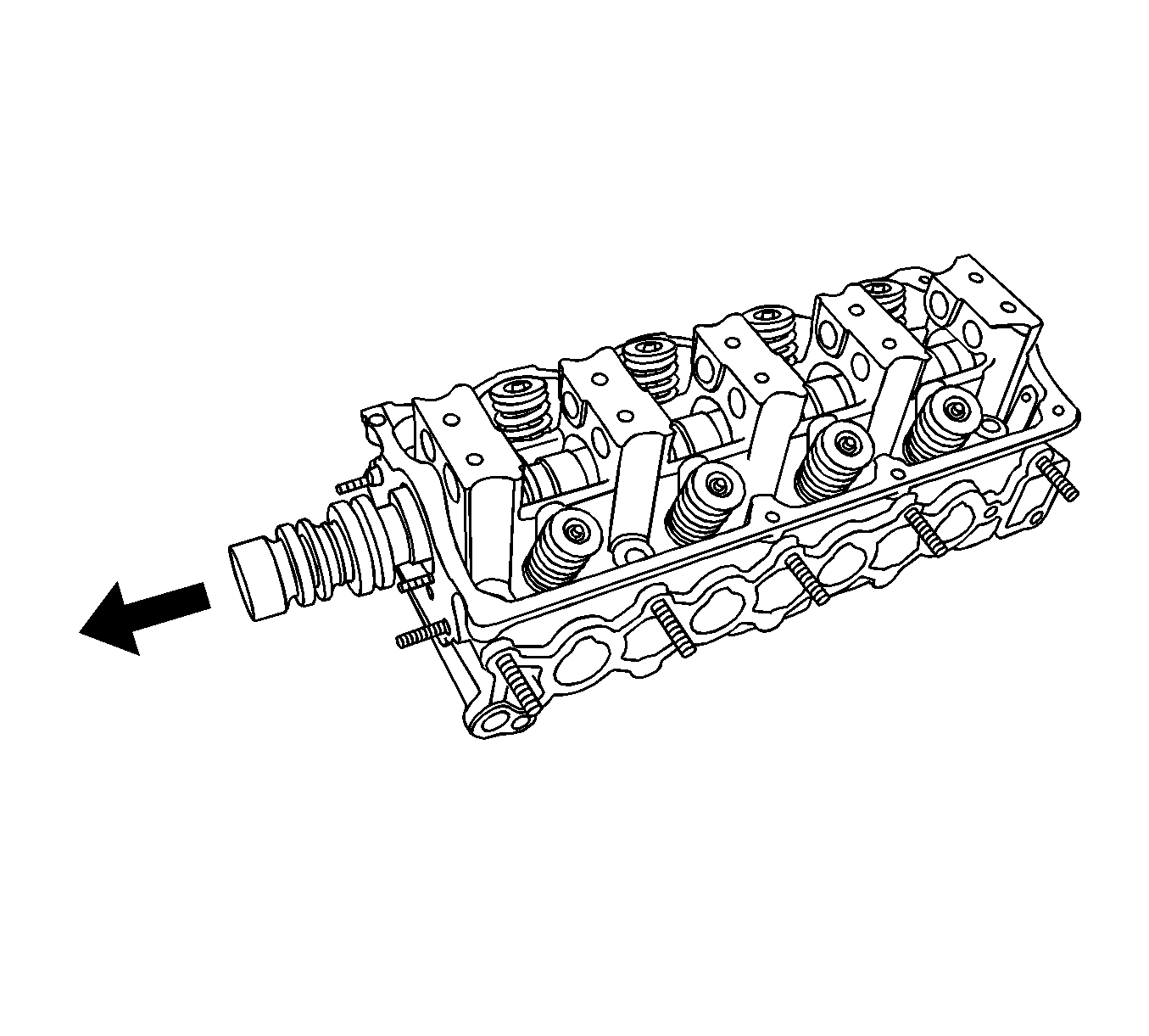
Notice: Use extreme care when installing the camshaft not to nick, scratch, or damage the camshaft lobes or bearing surfaces.
Notice: Refer to Fastener Notice in the Preface section.
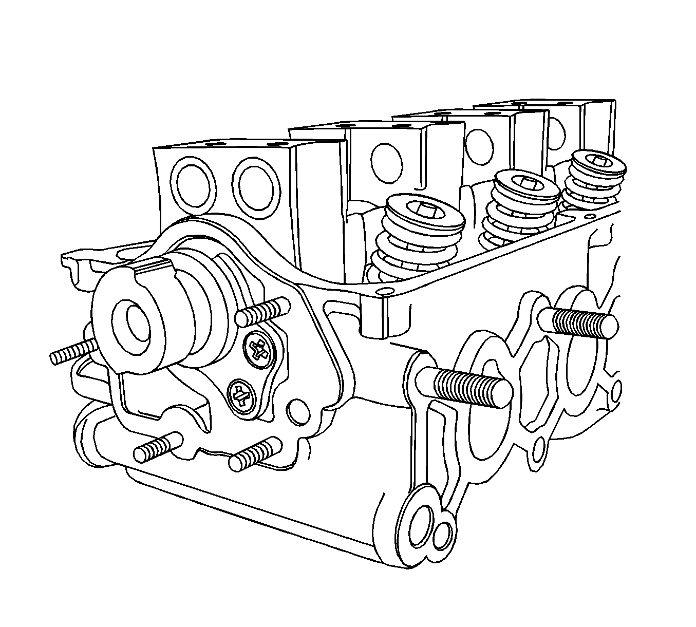
Tighten
Tighten the screws to 10 N·m (89 lb in).
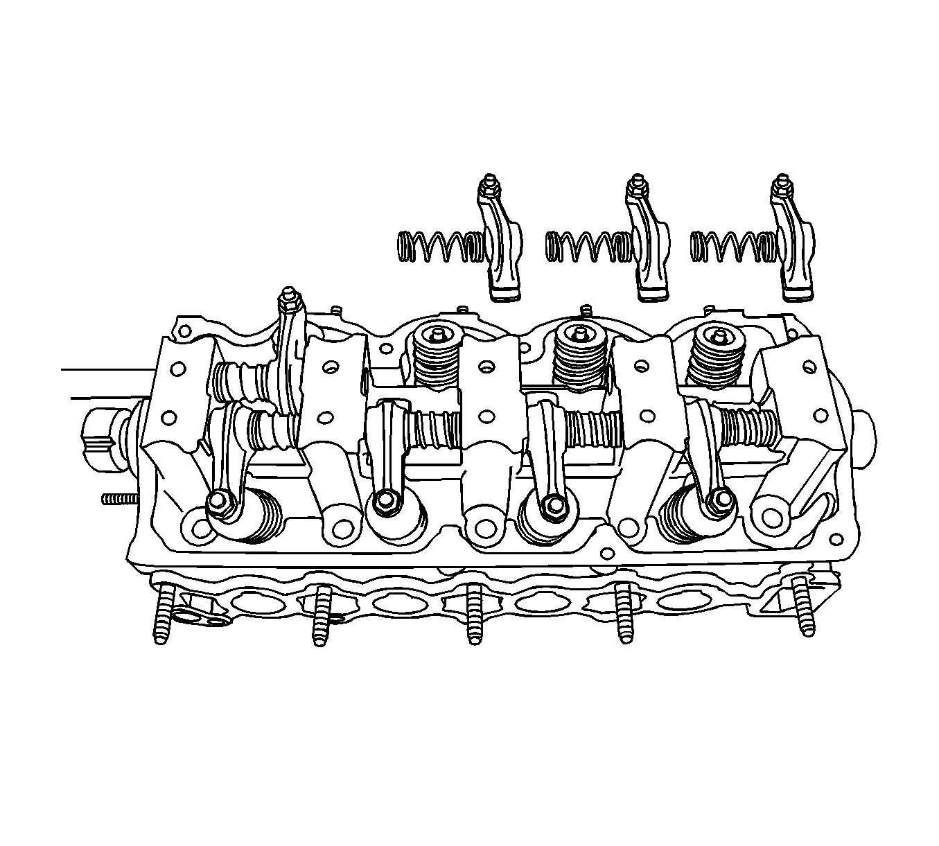
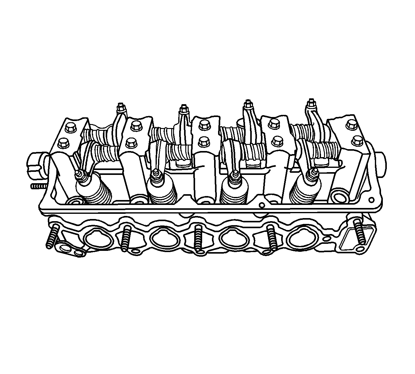
Important: The rocker arm shaft for the intake valves and the exhaust valves are different and their directions of installation are different.
Tighten
Tighten the bolts to 10 N·m (89 lb in).
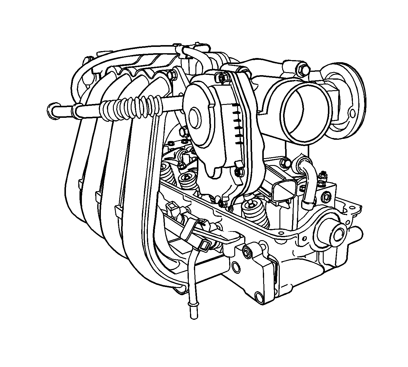
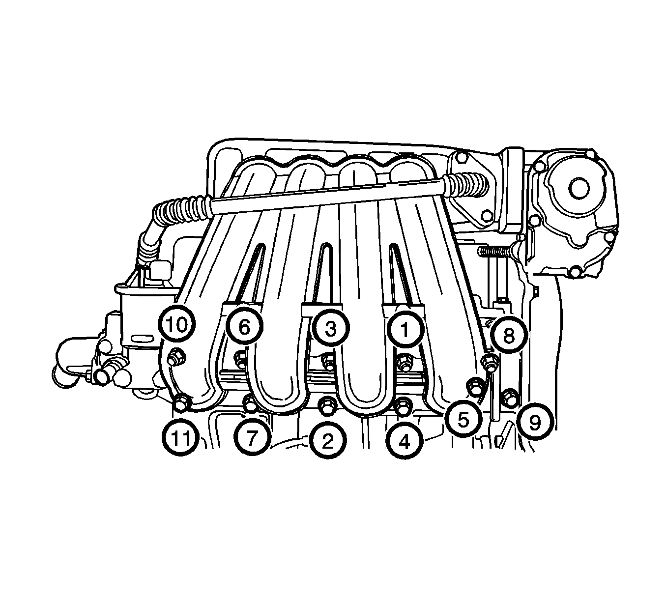
Important: Before tightening the intake manifold nuts, tighten the intake manifold support bracket nut.
Tighten
| • | Tighten the intake manifold nuts and the bolts to 17 N·m (13 lb ft). |
| • | Tighten the intake manifold bracket bolt to 10 N·m (89 lb in). |
Tighten
Tighten the exhaust manifold nuts and bolts to 22 N·m (16 lb ft).
Tighten
Tighten the exhaust manifold heat shield bolts to 10 N·m (89 lb in).
Tighten
Tighten the water outlet case mounting bolts to 10 N·m (89 lb in).
