For 1990-2009 cars only
Removal Procedure
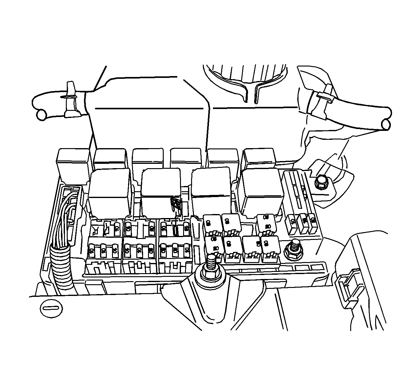
- Remove the fuel pump fuse.
- Start the engine. After it stalls, crank the engine for 10 seconds to rid the fuel system of fuel pressure.
- Disconnect the negative battery cable.
- Disconnect the engine control module (ECM) ground terminal from the intake manifold.
- Drain the engine coolant. Refer to Cooling System Draining and Filling .
- Disconnect the intake air temperature (IAT) sensor connector.
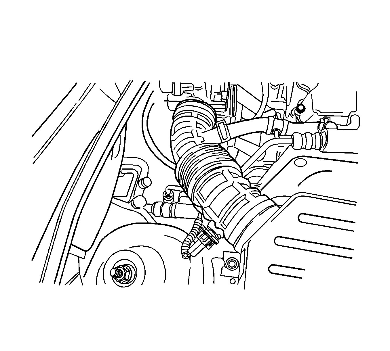
- Disconnect the air intake tube from the throttle body.
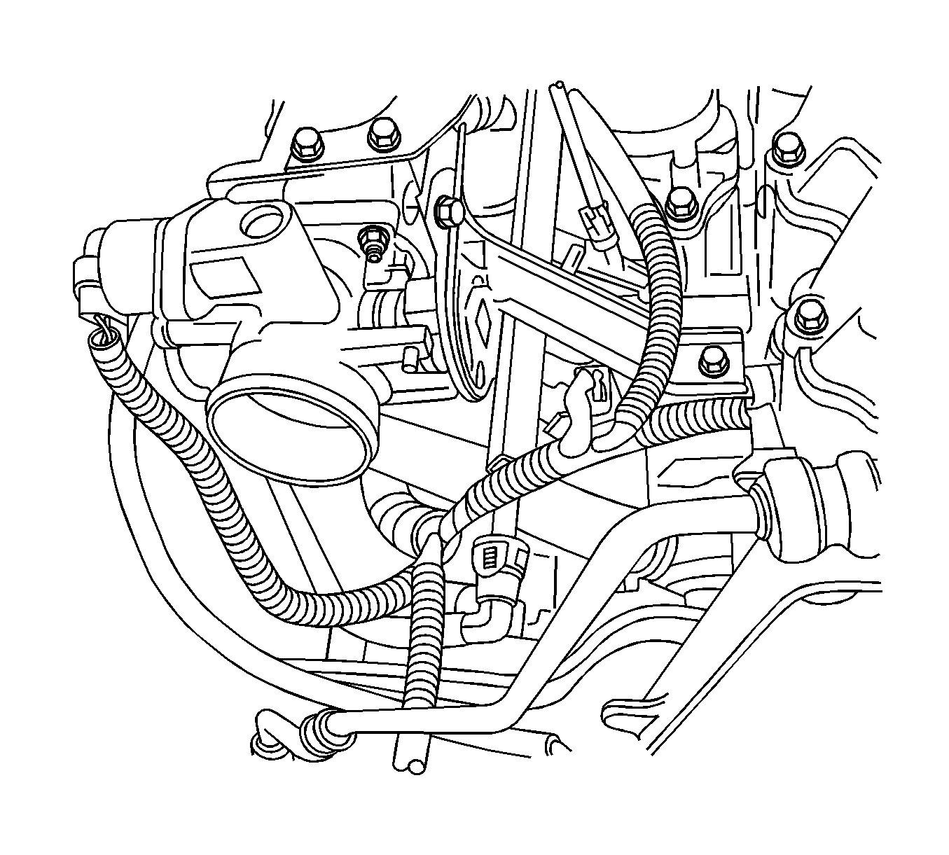
- Disconnect the idle air control valve (IAC) connector.
- Disconnect the throttle position (TP) sensor connector.
- Disconnect the heater inlet hose from the coolant distributor beneath the intake manifold.
- Disconnect the surge tank coolant hose at the throttle body.
- Disconnect all of the necessary vacuum hoses, including the vacuum hose at the fuel pressure regulator and the brake booster vacuum hose at the intake manifold.
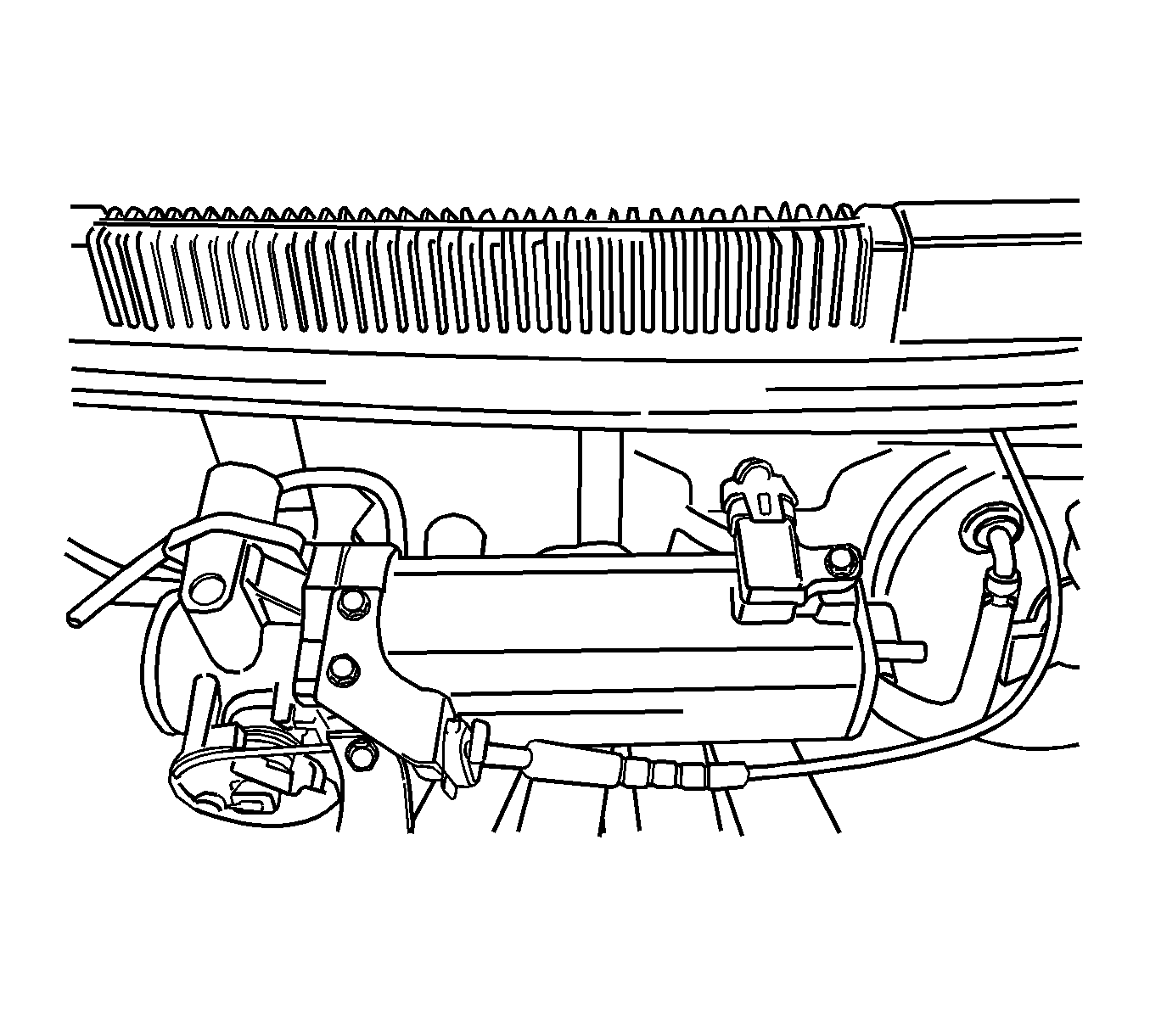
- Disconnect the throttle cable from the throttle body and the intake manifold.
- Remove the 2 throttle cable bracket bolts and the throttle cable bracket.
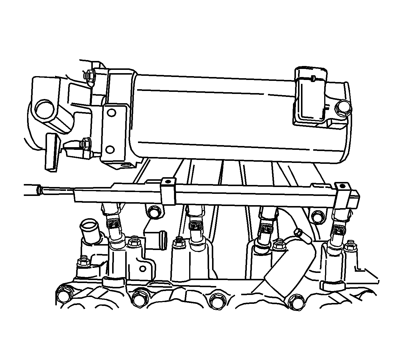
- Disconnect the fuel feed line from the fuel rail.
- Disconnect the fuel injector connectors from the fuel injectors.
- Remove the 2 retaining bolts from the fuel injector rail.
- Remove the fuel injector rail and fuel injectors as an assembly. Refer to Fuel Injection Fuel Rail Assembly Replacement .
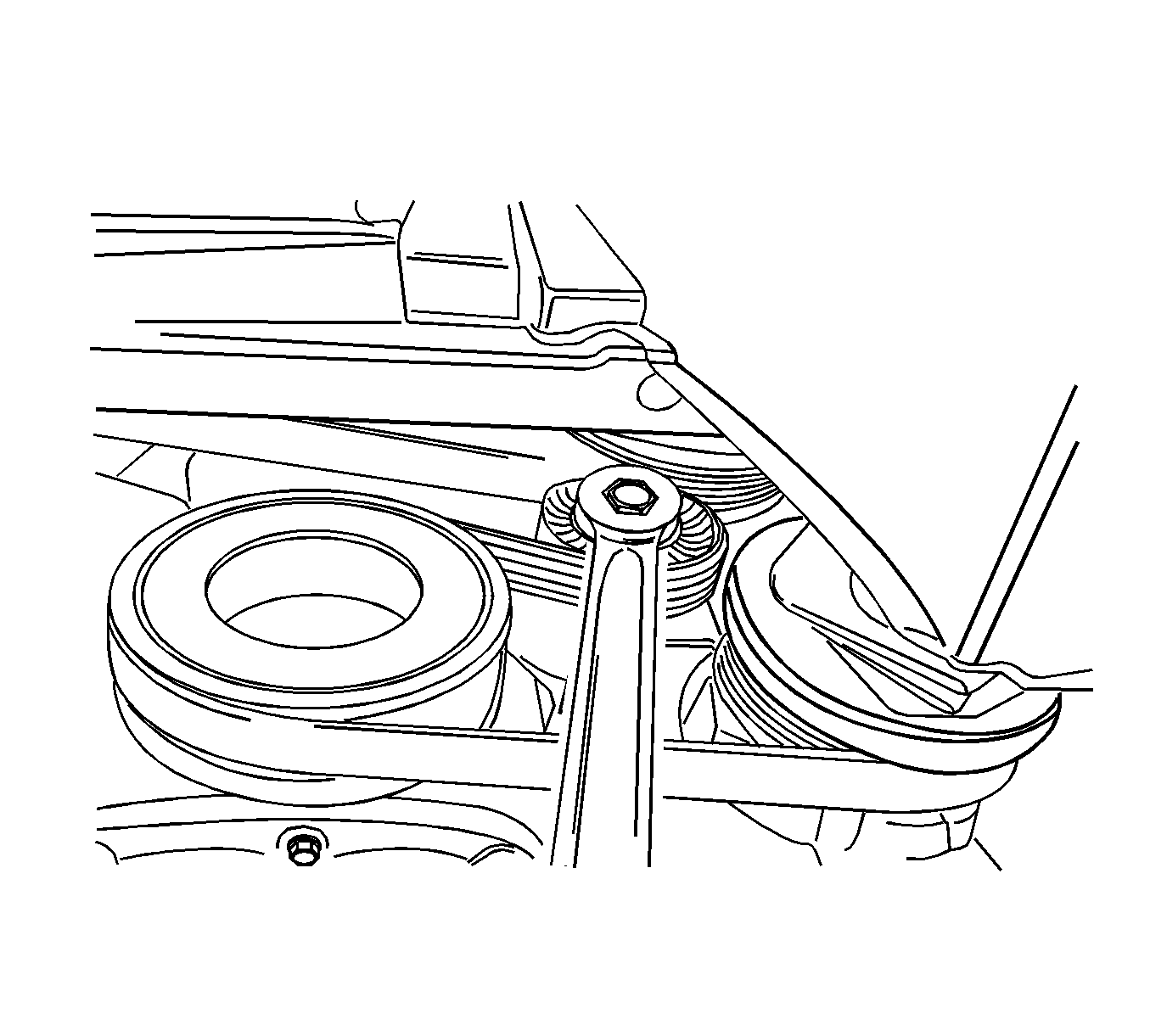
- Remove the serpentine accessory drive belt.
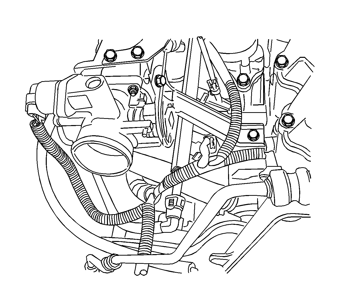
- Remove the alternator bracket and the bolt.
- Remove the 3 intake manifold support bracket retaining bolts from the coolant distributor and the engine block.
- Remove the intake manifold support bracket.
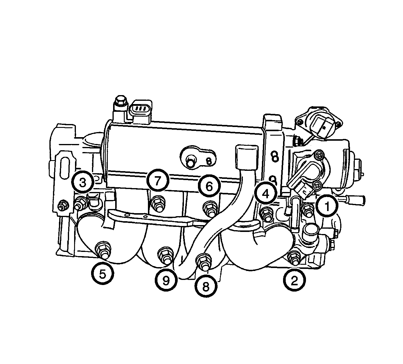
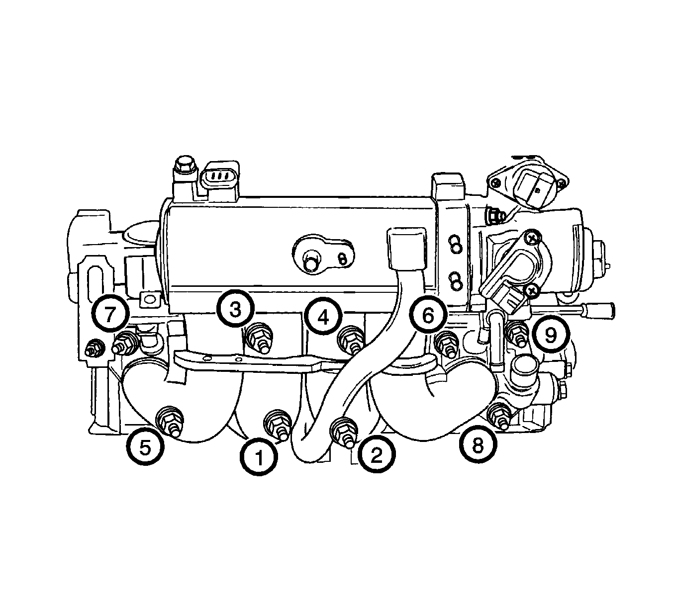
- Remove the intake manifold retaining nuts and the engine lift bracket bolt in the sequence shown.
- Remove the intake manifold.
- Remove the intake manifold gasket.
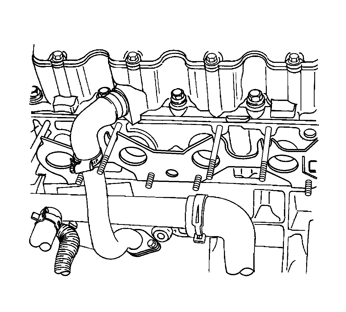
- Clean the sealing surfaces of the intake manifold and the cylinder head.
Caution: Refer to Battery Disconnect Caution in the Preface section.
Caution: Refer to Safety Glasses Caution in the Preface section.
Installation Procedure
- Install the intake manifold gasket.
- Install the intake manifold.
- Install the intake manifold retaining nuts and the engine lift bracket bolt in the sequence shown.
- Install the intake manifold support bracket.
- Install the intake manifold support bracket retaining bolts.
- Install the alternator bracket and the bolts.
- Install the serpentine accessory drive belt.
- Install the fuel rail and the fuel injectors as an assembly. Refer to Fuel Injection Fuel Rail Assembly Replacement .
- Install the fuel rail retaining bolts.
- Connect the fuel feed line to the fuel rail.
- Connect the throttle cable to the intake manifold and the throttle body.
- Connect the fuel injector connectors to the fuel injectors.
- Connect all of the vacuum lines that were previously disconnected.
- Connect the heater inlet hose to the coolant distributor beneath the intake manifold.
- Connect the surge tank coolant hose to the throttle body.
- Connect the IAC valve connector.
- Connect the throttle position sensor connector.
- Connect the air intake tube to the throttle body.
- Connect the IAT sensor connector.
- Connect the ECM ground terminal to the intake manifold.
- Connect the negative battery cable.
- Install the fuel pump fuse.
- Refill the engine cooling system. Refer to Cooling System Draining and Filling .
Notice: Refer to Fastener Notice in the Preface section.
Tighten
| • | Tighten the intake manifold retaining nuts in the sequence shown to 22 N·m (16 lb ft). |
| • | Tighten the engine lift bracket bolt to 25 N·m (18 lb ft). |

Tighten
Tighten the intake manifold support bracket retaining bolts to 25 N·m (18 lb ft).
Tighten
Tighten the alternator bracket retaining bolts to 25 N·m (18 lb ft).
Notice: Refer to Belt Dressing Notice in the Preface section.

Tighten
Tighten the fuel rail retaining bolts to 25 N·m (18 lb ft).


