- Shift the transaxle into NEUTRAL.

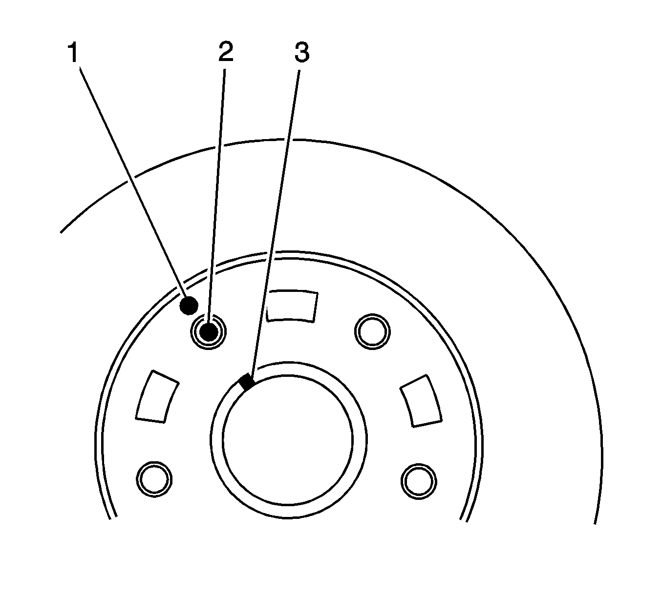
- Use paint in order to mark the relative position of the following components:
- Remove the brake rotor. Refer to
Brake Rotor Replacement
.
Important: Rust or contaminants on the hub flange or on the brake rotor mating surfaces may cause excessive brake rotor assembled lateral runout (LRO), which could lead to brake pulsation.
- Inspect the mating surfaces of the hub flange and the brake rotor. Ensure the mating surfaces are clean and free from burrs.
- Clean the brake pad lining contact surfaces of the brake rotor.
Important: There are 2 different brake rotor sizes available for this vehicle.
- Measure the diameter of the brake rotor in order to determine which set of specifications apply to the vehicle.
- Align the marks and install the rotor to the hub flange.
Notice: Refer to Fastener Notice in the Preface section.
- Install the 2 detent screws in order to retain the rotor to the hub.
Tighten
Tighten the detent screws to 4 N·m (35 lb ft).

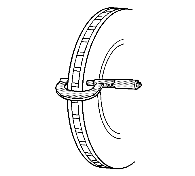
- Use a micrometer in order to measure the thickness of the brake rotor. Measure the thickness of the rotor
at 4 or more points equally spaced around the rotor. Position the micrometer the same distance from the outside edge of the rotor, in the brake pad lining contact area.
- Compare the measurements to the following specifications:
Specifications
| • | The thickness of a new 236 mm (9.29 in) diameter brake rotor is 20 mm (0.787 in). |
| • | The discard specification for the 236 mm (9.29 in) diameter brake rotor is 18 mm (0.709 in). |
| • | The thickness of a new 256 mm (10.08 in) diameter brake rotor is 24 mm (0.945 in). |
| • | The discard specification for the 256 mm (10.08 in) diameter brake rotor is 22 mm (0.866 in). |
- If the smallest measurement exceeds the discard specification, you may be able to resurface the brake rotor, depending upon the thickness variation and the surface condition.
Important: Both rotors must have identical surfaces regarding smoothness and scoring depth in order to provide uniform braking on both sides of the vehicle. For this reason, always replace both brake rotors
- If the smallest measurement is equal to or less than the discard specification, replace both brake rotors. Refer to
Brake Rotor Replacement
.
- Calculate the difference between the largest and the smallest thickness measurements in order to determine the amount of thickness variation.
- Compare the thickness variation measurements to the following specification:
Specification
The maximum thickness variation of the rotor is 0.10 mm (0.004 in).
Important: Brake rotor thickness variation greater than the specification can cause brake pulsation.
- If the brake rotor thickness variation measurement exceeds the specification, you may be able to resurface the brake rotor, depending upon the surface condition and the assembled lateral runout (LRO).
- Inspect the braking surfaces of the brake rotor for the following conditions:
| • | Heavy rust and/or pitting |
| • | Cracks and/or heat spots |
| • | Excessive blue discoloration |
- If the braking surfaces of the brake rotor exhibit one or more of the braking surface conditions, you may be able to resurface the brake rotor, depending upon the depth of the grooves and the LRO.
- Use a micrometer in order to measure any grooves on the rotor braking surfaces.
- Compare the groove depth to the following specification:
Specification
The maximum groove depth is 0.40 mm (0.016 in).
- If the groove depth exceeds the specification, or if an excessive amount of scoring is present, you may be able to resurface the brake rotor, depending upon the LRO.

Important: Brake rotor LRO exceeding the maximum allowable specification can cause thickness variation to develop in the brake rotor over time, usually between 4800-11300 km (3000-7000 mi).
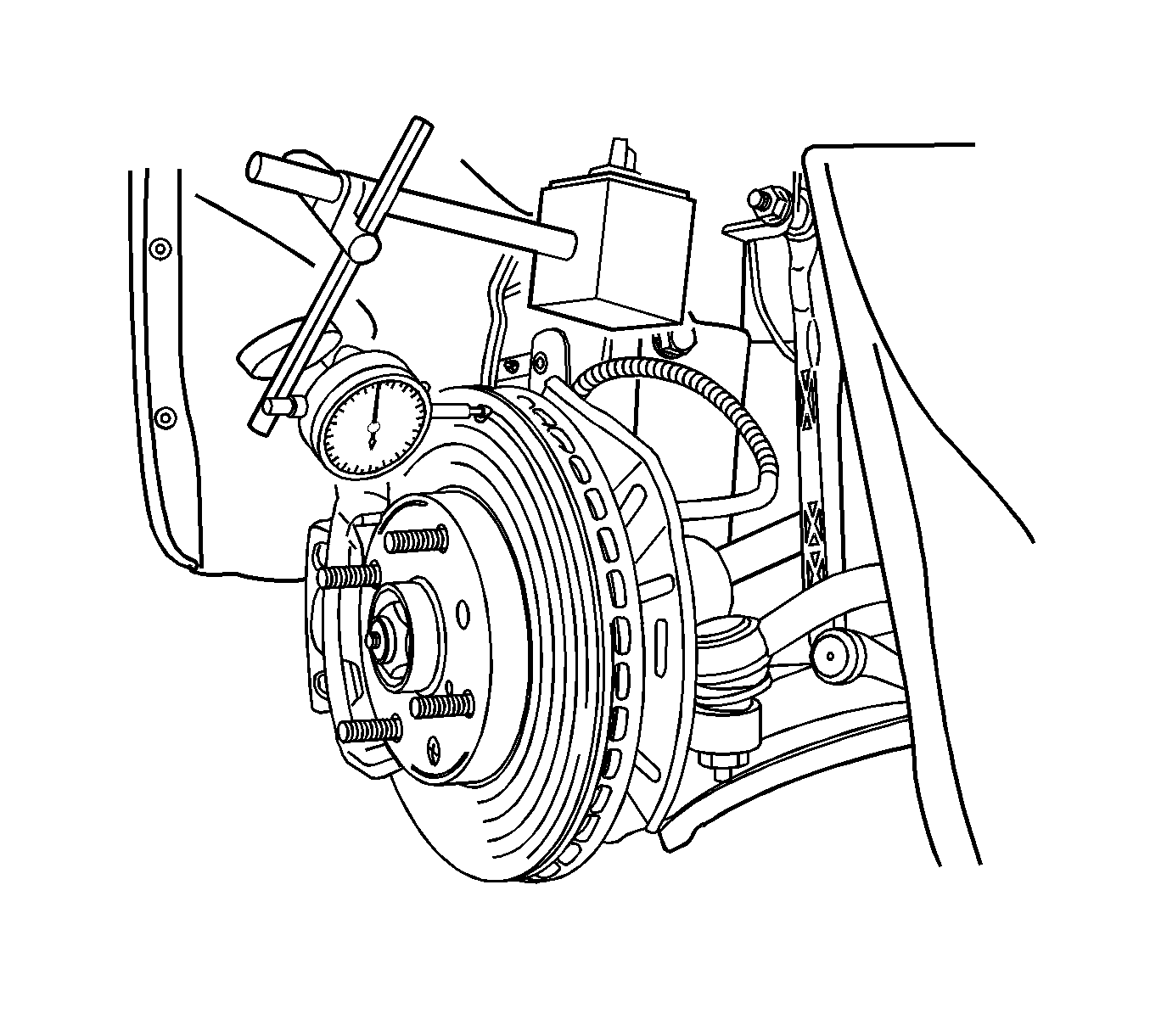
- Perform the following steps in order to measure and record the assembled LRO of the rotor:
| 21.1. | Install the dial indicator to the vehicle. Position the indicator button in the brake rotor friction surface area 10 mm (0.39 in) from the outer edge of the brake rotor. |
| 21.2. | Verify the indicator is at a 90 degree angle to the rotor. |
| 21.3. | Rotate the rotor until the indicator displays the lowest reading. |
| 21.4. | Set the dial to zero. |
| 21.5. | Rotate the rotor until the indicator displays the highest reading. |
| 21.6. | Mark the location of the high spot relative to the nearest wheel stud or studs. |
| 21.7. | Measure and record the amount of LRO. |
- Compare the LRO to the following specification:
Specification
The maximum allowable LRO is 0.06 mm (0.002 in).
- If the measurements of the rotor are within the specifications, remove the dial indicator and complete the installation of the rotor and the pads. Refer to
Brake Rotor Replacement
.
Important: Accurate control of the rotor tolerances is necessary for proper performance of the disc brakes. Use precision equipment for refinishing the rotor.
- If the LRO measurement EXCEEDS the specification, refinish the rotor in order to attain true parallelism.
- Verify the measurements of the rotor are within the specifications.
- If the measurements of the rotor are within the specifications, complete the installation of the rotor and the pads. Refer to
Brake Rotor Replacement
.


