Tools Required
| • | J 8062 (KM-348) Valve Spring Compressor - Head Off |
| • | KM-653-A Adapter |
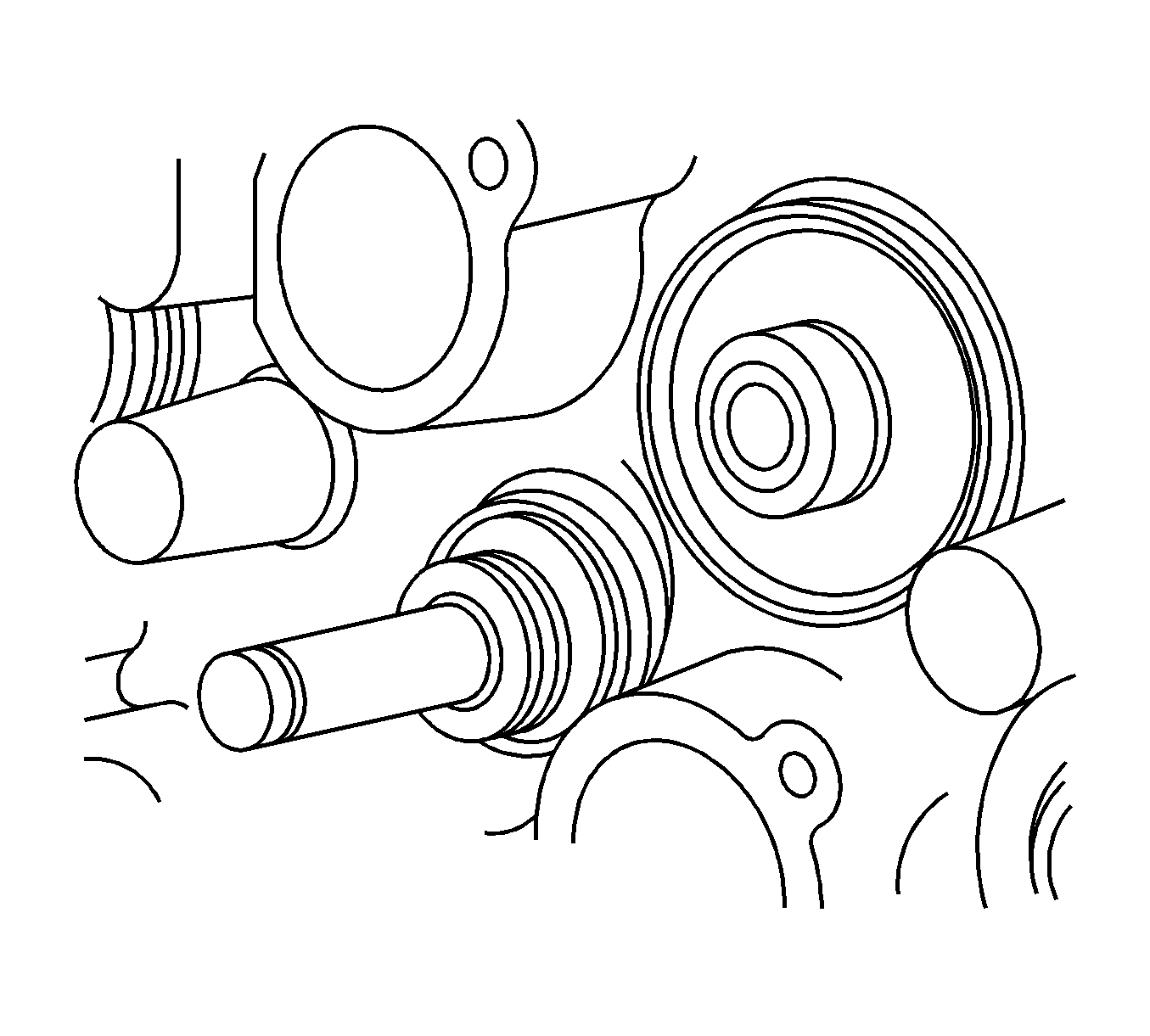
- Install new valve stem seals.
- Lubricate the valve stems with engine oil.
- Carefully install the valves in their original positions. Do not damage the valve stem seals.
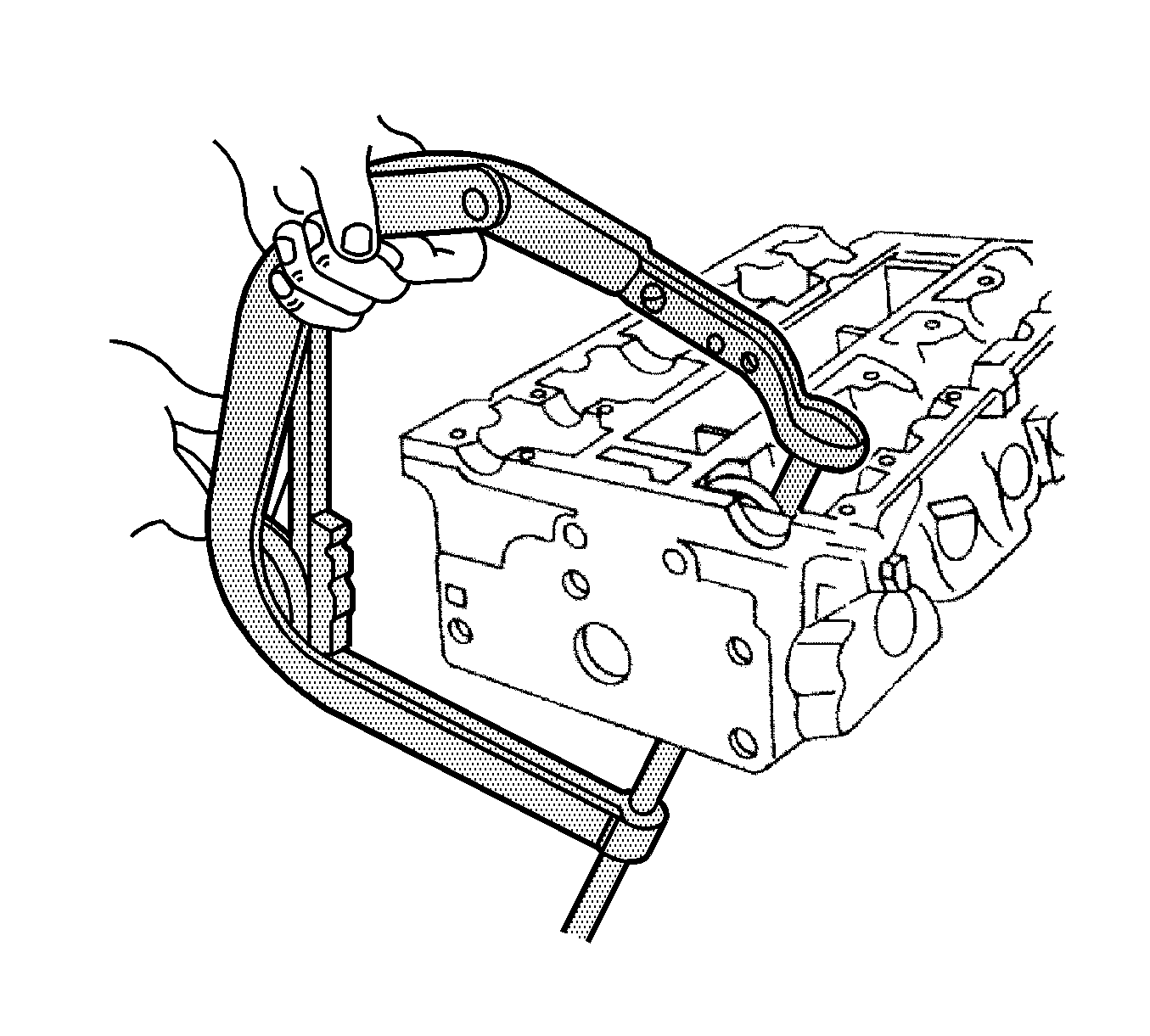
- Install the valve springs in their original positions.
- Install the valve spring caps.
- Compress the valve springs with J 8062 and KM-653-A .
- Install the valve keys.
- Remove J 8062 and KM-653-A .
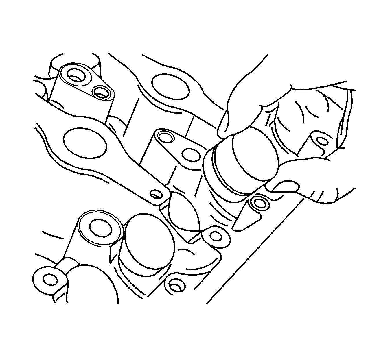
- Lubricate the valve tappet adjusters with engine oil.
- Install the valve tappet adjusters.
- Install the intake camshaft.
- Install the intake camshaft caps in their original positions.
- Install the exhaust camshaft.
- Install the exhaust camshaft caps in their original positions.
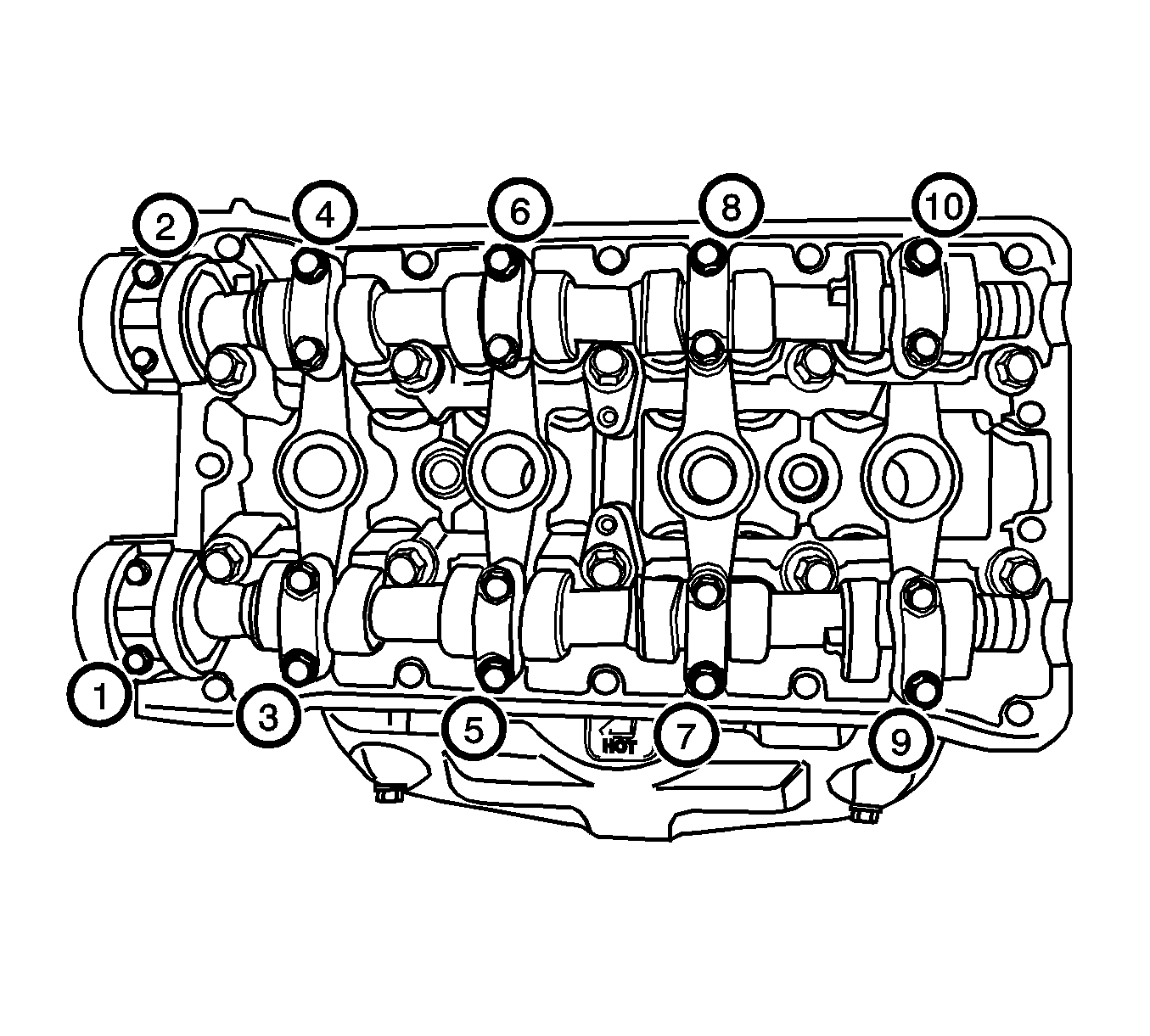
- Install the camshaft cap bolts.
- Tighten the camshaft cap bolts gradually and in the sequence shown for each camshaft cap.
- Install the spark plugs.
- Install the exhaust gas recirculation (EGR) valve adapter gasket.
- Install the EGR valve adapter.
- Install the EGR valve adapter bolts.
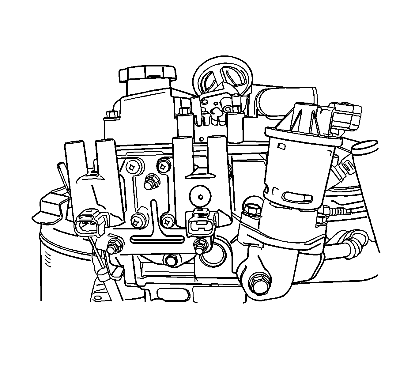
- Install the direct ignition system (DIS) coil mounting bracket.
- Install the DIS coil mounting bracket bolts.
- Install the DIS coil with the ignition wires attached.
- Install the DIS coil mounting bolts.
- Install the intake manifold studs.
- Install the intake manifold.
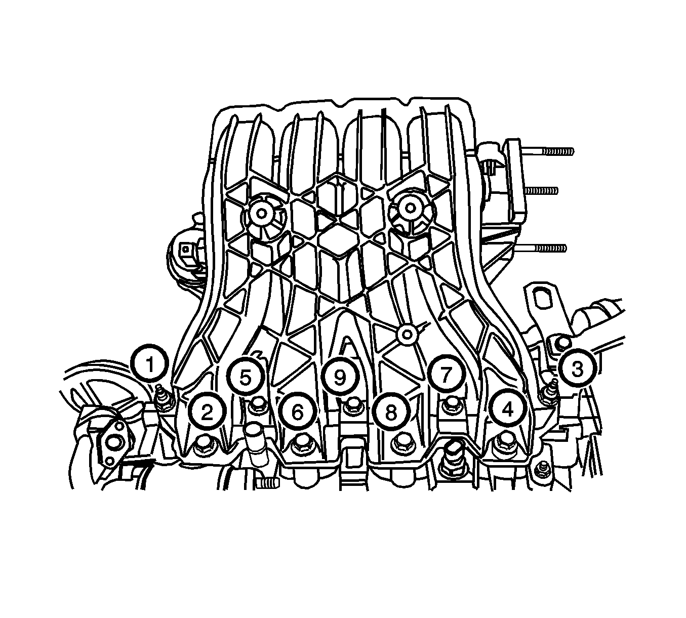
- Install the intake manifold retaining nuts and retaining bolts in the sequence shown.
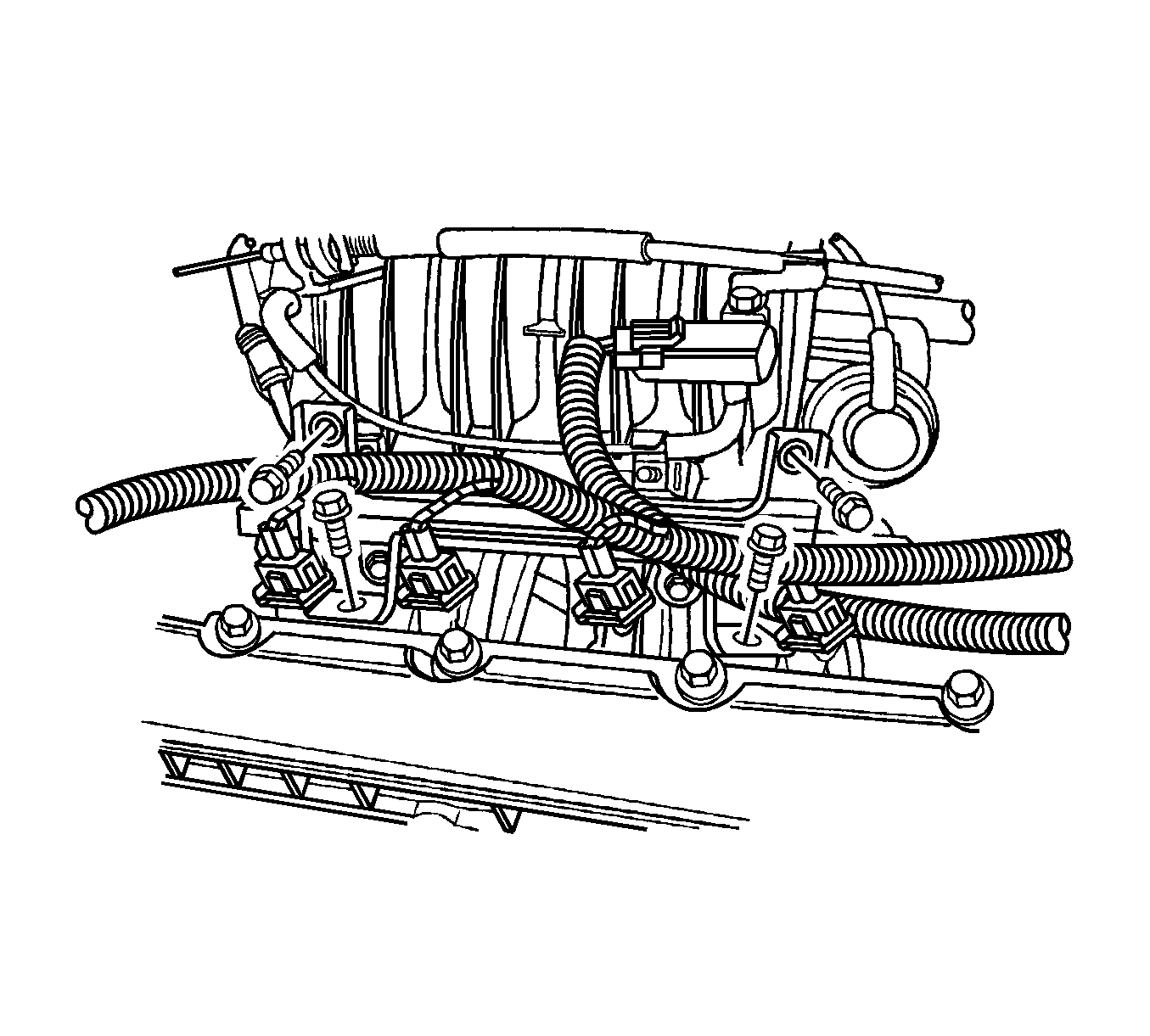
- Install the fuel rail assembly with the bolts.
- Install the thermostat housing assembly.
- Install the thermostat housing mounting bolts.
- Install the exhaust manifold studs.
- Install the exhaust manifold gasket.
- Install the exhaust manifold.
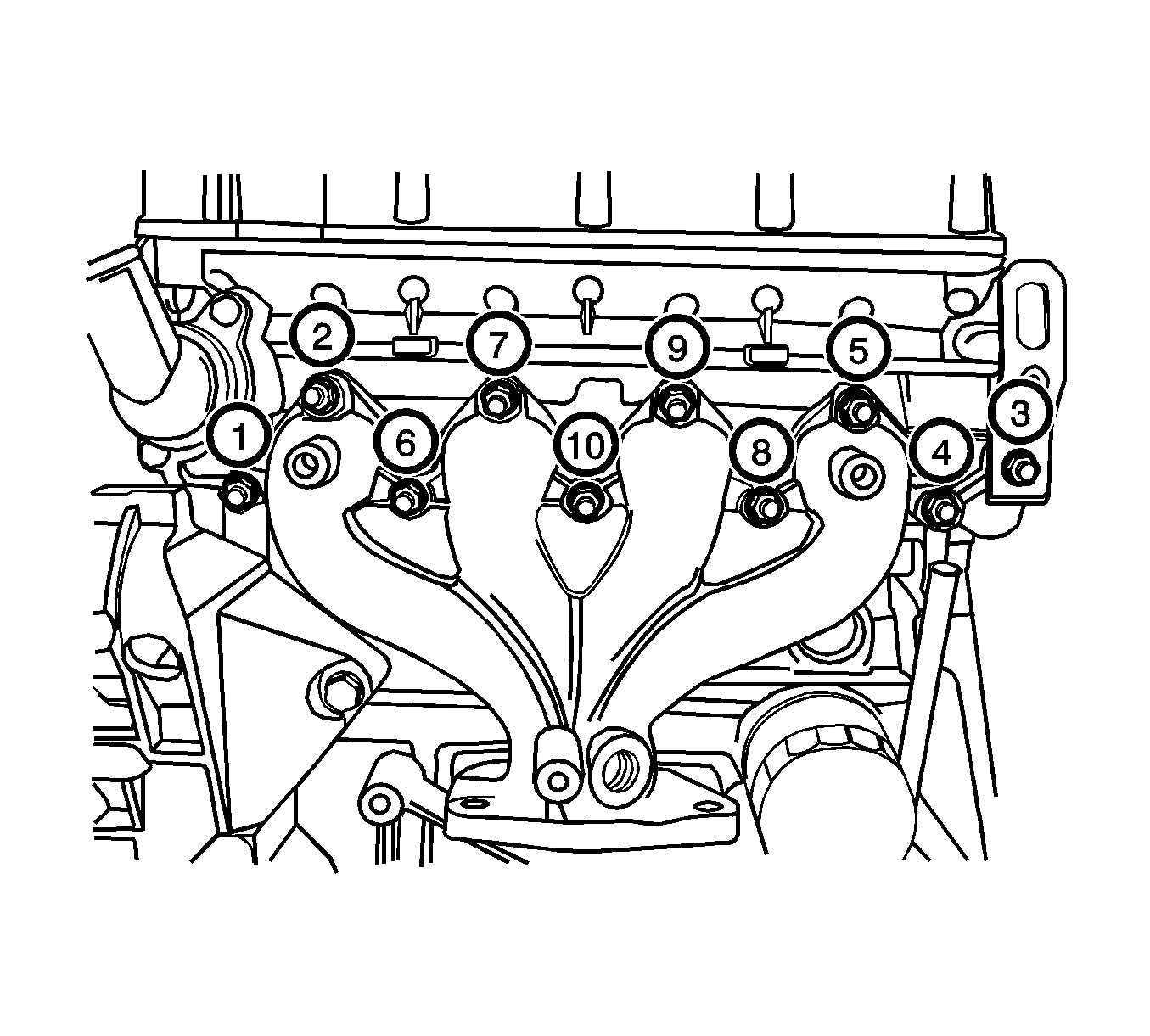
- Install the exhaust manifold retaining nuts in the sequence shown.
- Install the exhaust manifold heat shield.
- Install the exhaust manifold heat shield bolts.
- Install the coolant temperature sensor.
- Install the cylinder head with the intake manifold and the exhaust manifold attached. Refer to Cylinder Head Replacement .
Notice: Refer to Fastener Notice in the Preface section.
Tighten
Tighten the camshaft cap bolts to 16 N·m (12 lb ft).
Tighten
Tighten the spark plugs to 25 N·m (18 lb ft).
Tighten
Tighten the exhaust gas recirculation valve adapter bolts to 25 N·m (18 lb ft).
Tighten
Tighten the direct ignition system coil mounting bracket bolts to 10 N·m (89 lb in).
Tighten
Tighten the direct ignition system coil mounting bolts to 10 N·m (89 lb in).
Tighten
Tighten the intake manifold retaining nuts and retaining bolts to 25 N·m (18 lb ft).
Tighten
Tighten the fuel rail assembly retaining bolts to 25 N·m (18 lb ft).
Tighten
Tighten the thermostat housing mounting bolts 20 N·m (15 lb ft).
Tighten
Tighten the exhaust manifold retaining nuts to 25 N·m (18 lb ft).
Tighten
Tighten the exhaust manifold heat shield bolts to 15 N·m (11 lb ft).
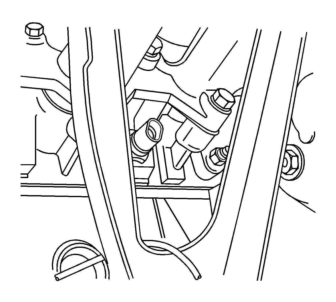
Tighten
Tighten the coolant temperature sensor to 20 N·m (15 lb ft).
