For 1990-2009 cars only
Removal Procedure
- Raise and support the vehicle. Refer to Lifting and Jacking the Vehicle .
- Remove the front tire and wheel assemblies. Refer to Tire and Wheel Removal and Installation .
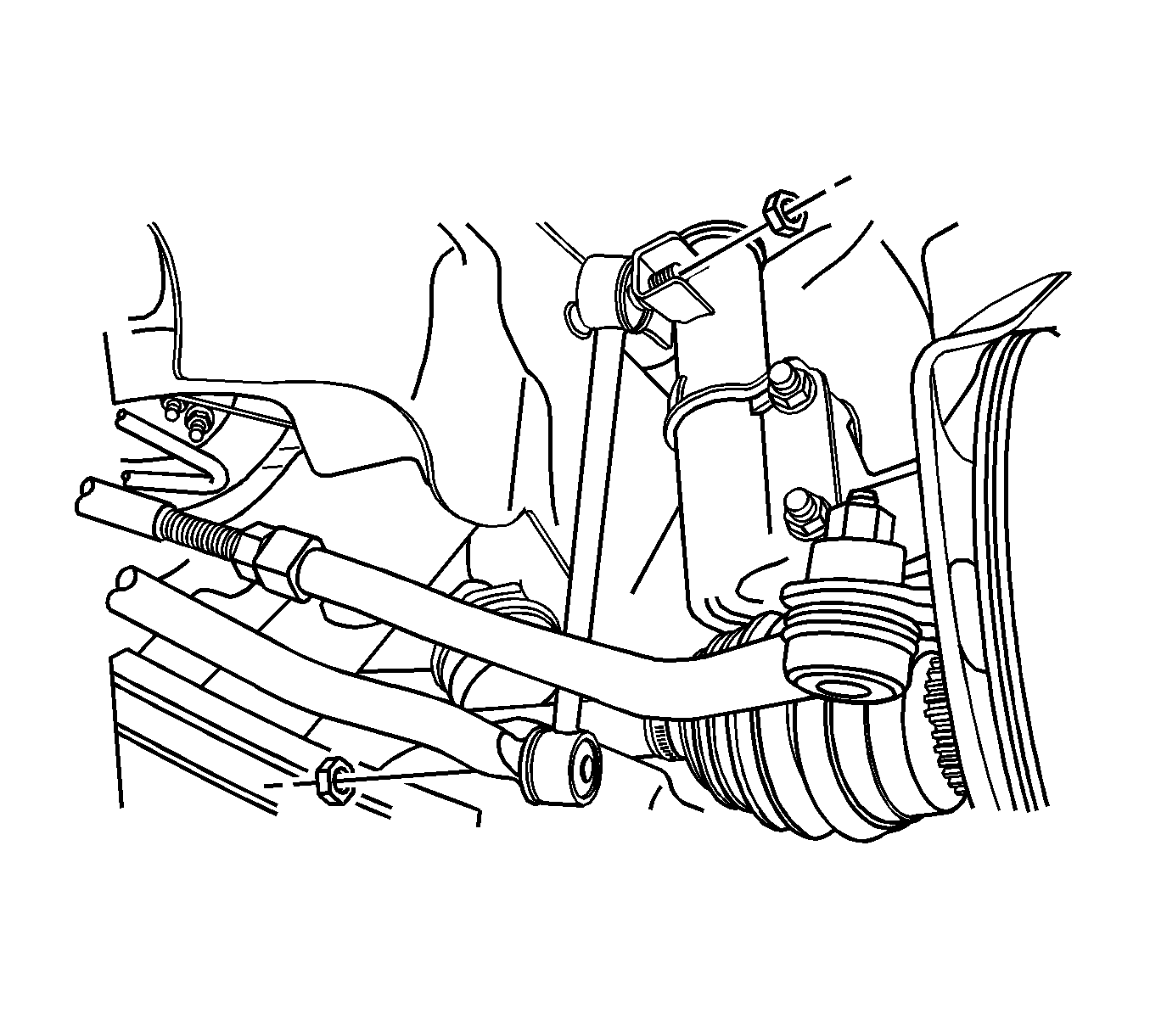
- Remove the control arm ball joint and stabilizer shaft link nut, lower.
- Remove the tie rod end ball joint.
- Remove the engine mounting reaction rod bolts.
- Drain the power steering fluid.
- Remove the power steering pipe fittings.
- Remove the intermediate shaft lower joint.
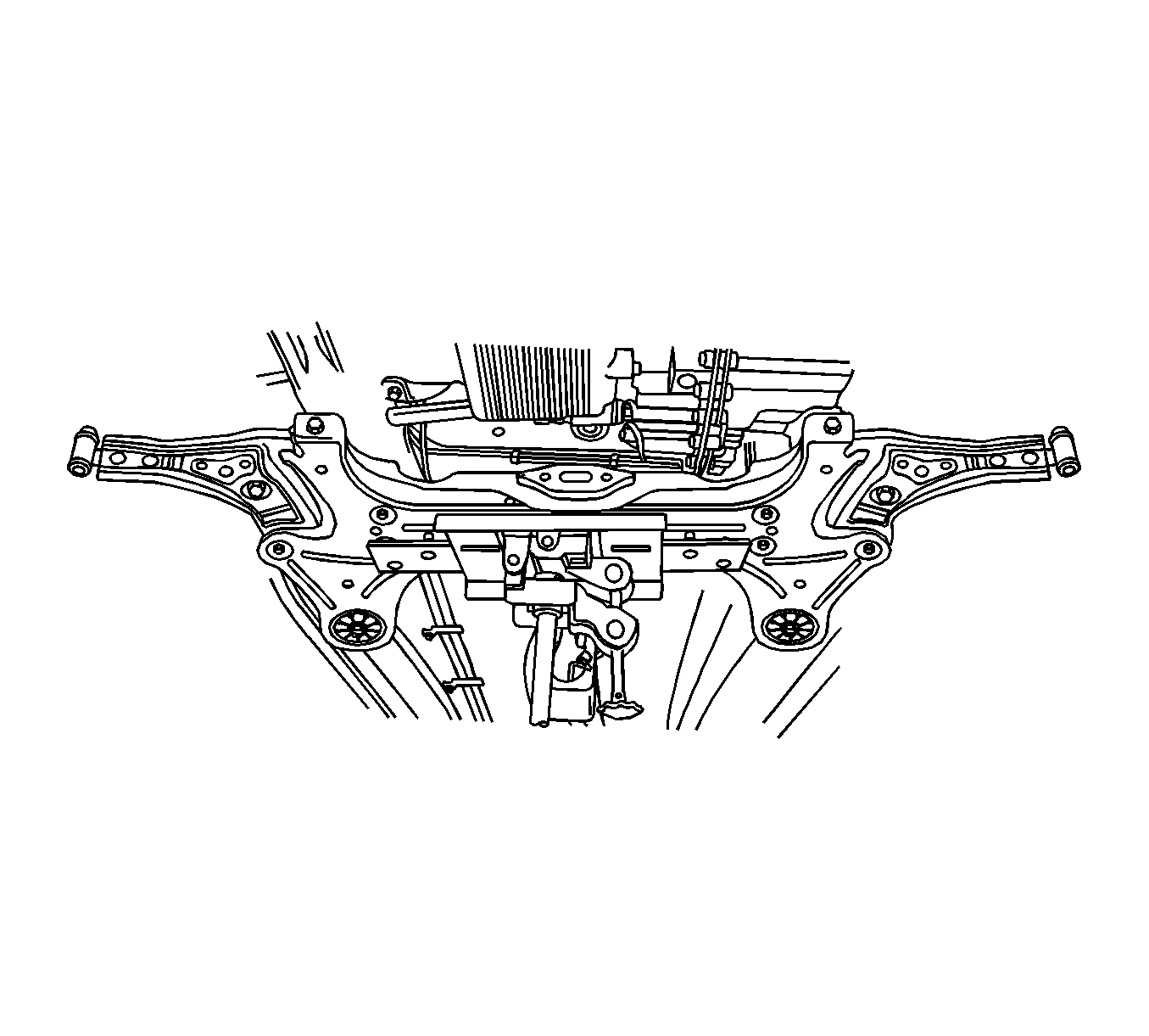
- Remove the crossmember assembly.
- Remove the stabilizer bar, power steering gear set, and control arm from the crossmember.
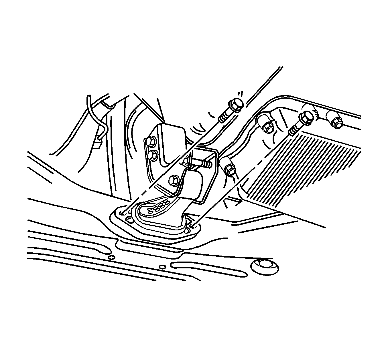
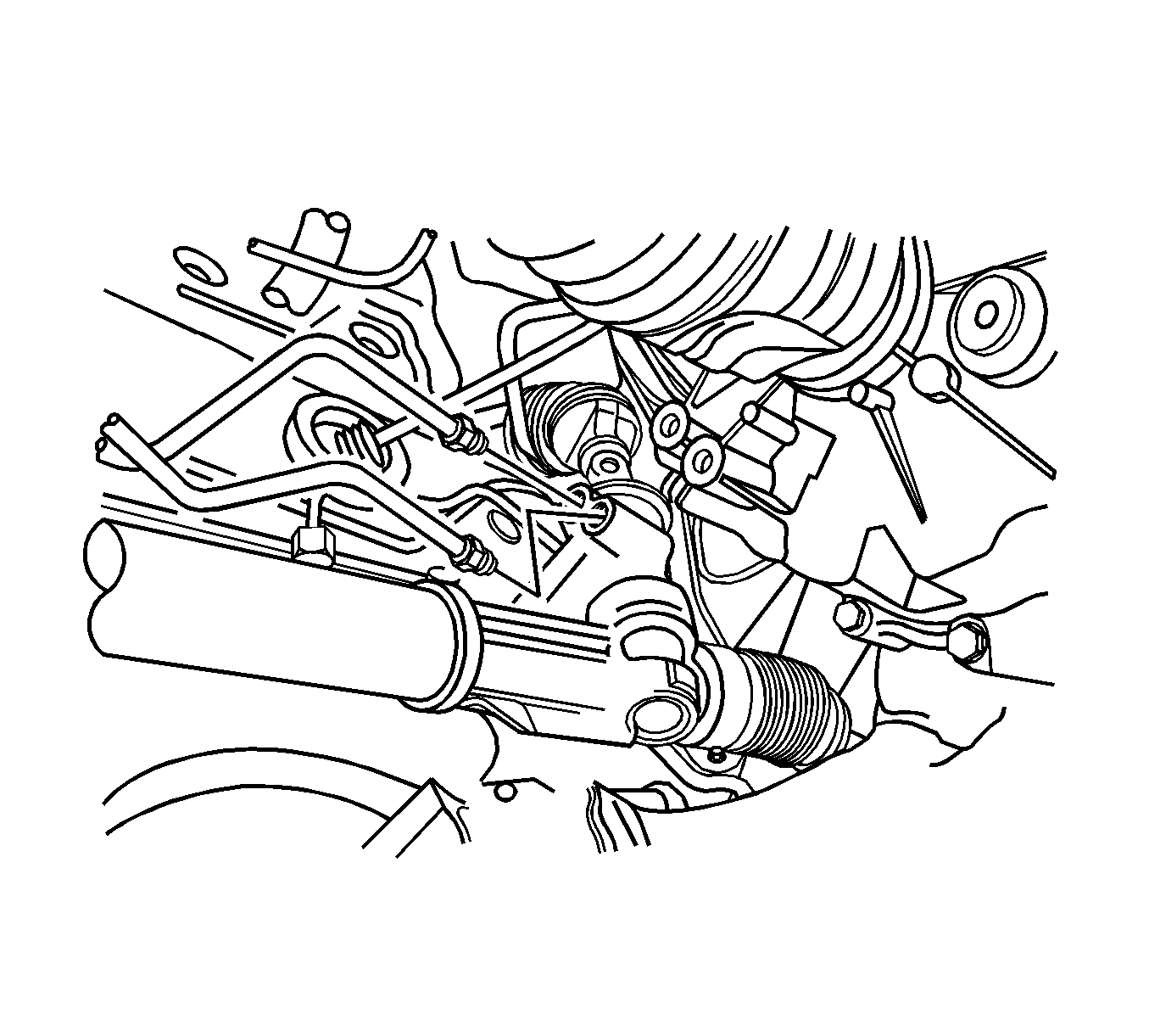
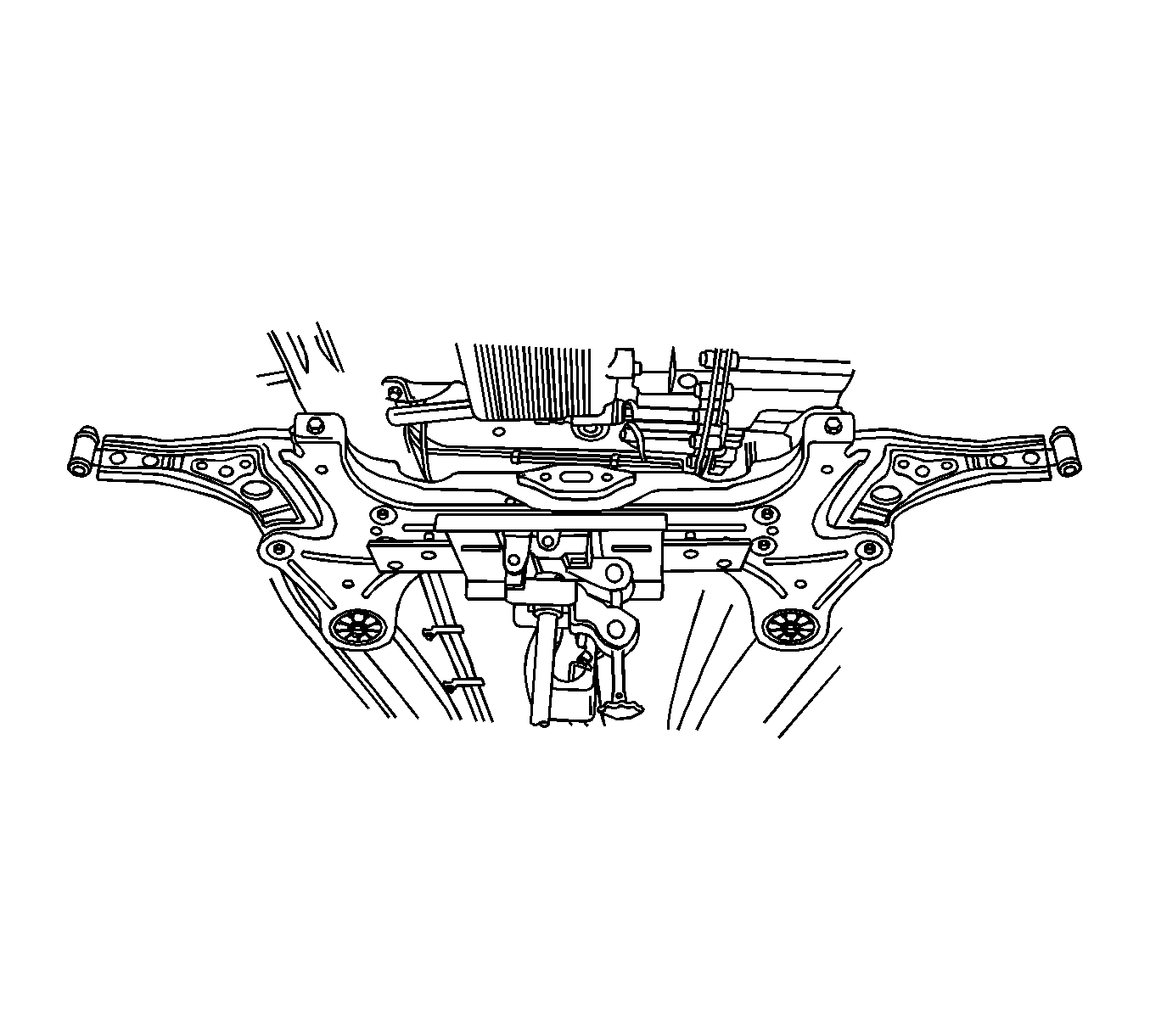
Caution: Failure to support crossmember can cause crossmember to drop to the ground when crossmember mounting bolts are removed.
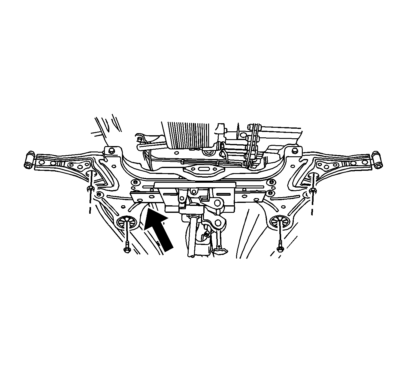
Installation Procedure
- Install the stabilizer bar, power steering gear set, and control arm from the crossmember.
- Install the crossmember assembly front to body nut and the crossmember assembly rear to body bolt.
- Connect the intermediate shaft lower joint and power steering pipe fittings.
- Install the engine mounting reaction rod bolts.
- Install the tie rod end ball joint nut.
- Install the control arm ball joint and stabilizer shaft link nut, lower.
- Install the front tire and wheel assemblies. Refer to Tire and Wheel Removal and Installation .
- Lower the vehicle.
Notice: Refer to Fastener Notice in the Preface section.
Tighten
Tighten the crossmember assembly front to body nut and rear to body bolt to 150 N·m (111 lb ft).

Tighten
Tighten the power steering pipe fittings to 22 N·m (16 lb ft).

Tighten
Tighten the engine mounting reaction rod bolts to 60 N·m (44 lb ft).
Tighten
Tighten the tie rod end ball joint nut to 45 N·m (33 lb ft).
