LXT, L91, Poor Acceleration, Throttle Body Frozen Shut and/or Stuck Closed, MIL/SES Light On, DTCs P1516, P2106, P2110 Set in Extremely Low Temperatures with High Humidity After Cold Engine Start

| Subject: | LXT, L91, Poor Acceleration, Throttle Body Frozen Shut and/or Stuck Closed, MIL/SES Light Illuminated, DTC'S P1516, P2106 and/or P2110 Set in Extremely LowTemperatures with High Humidity Condition After an Initial Cold Engine Start or While Driving, Reduced Engine Modes (Install PCV Valve Kit and Reprogram ECM) |
| Models: | 2006-2008 Chevrolet Aveo |
| 2006-2008 Pontiac Wave (Canada Only) |
| with 1.6L 4-Cylinder Engine (VIN 6 - RPOs LXT, L91) |
Condition
Some customers may comment on poor acceleration and/or reduced engine power with an MIL/SES light illuminated after an initial cold engine start or while driving. Upon further investigation, technicians may find the throttle body frozen shut or stuck closed in extremely low temperatures with high humidity condition with the following DTC's:
P2106 and P2110 indicate that a throttle actuator control (TAC) DTC is set. This causes the engine control module (ECM) to command one of the following Reduced Power Modes:
| • | P1516: Throttle Actuator Control (TAC) Module Throttle Actuator Position Performance |
| • | P2106: Throttle Control System Performance - Throttle Limitation Active |
| • | P2110: Throttle Actuator Control (TAC) System - Forced Limited Engine Speed |
Correction
Perform the steps outlined in this bulletin to install the PCV valve kit and reprogram the ECM.
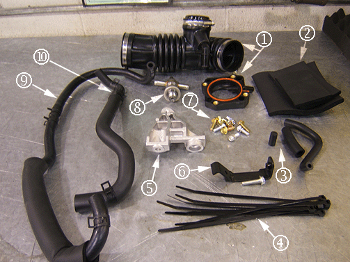
PCV Valve Kit Components
- Air Outlet Duct Assembly -- P/N 96889507
- Crankcase Breather and PCV Valve Hose Insulators
- Map Sensor Vacuum Tube, Throttle Body Adapter Hose and Intake Manifold Vacuum Plug
- Left and Right Side Crankcase Breather hose Insulator Tie-Straps (Qty 6) P/N 94530232
- PCV Valve Hose Insulator Tie-Straps (Qty10) P/N 12337820, are Not part of the kit must be ordered from GMSPO.
- Engine Shackle Bracket -- P/N 96892600
- Map Sensor Bracket -- P/N 96891920
- Throttle Body and Adapter Bolts/Screws
- PCV Valve Assembly -- P/N 96942679
- Throttle Body Heater Coolant Inlet Hose Assembly -- P/N 96887066
- Crankcase Vent Hose Assembly -- P/N 96896825
-- Throttle Body Adapter Assembly -- P/N 96875544
| 2.1. | PCV Valve Hose -- P/N 96896827, Insulator size 60 mm x 100mm (2.4 in x 3.9 in) |
| 2.2. | Breather Hose Right Side of PCV Valve -- P/N 96942680, Insulator size 80 mm x 130 mm (3.1 in x 5.1 in) |
| 2.3. | Breather Hose Left Side of PCV Valve -- P/N 96942681, Insulator size 130 mm x 145 mm (5.1 in x 5.7 in) |
| 3.1. | Map Sensor Vacuum Tube Assembly -- P/N 96891970 |
| 3.2. | PCV Valve to Throttle Body Adapter Hose -- P/N 96943257 |
| 3.3. | Intake Manifold Vacuum Hole Plug -- P/N 96351328 |
Important: Discard the two white tie-straps provided in the kit. Use only two of the new tie-straps, P/N 12337820, and retain the extra tie-straps for the next PCV Valve Kit to be installed.
-- Map Sensor Bracket Bolt/Screw -- P/N 94500414
| 7.1. | Allen Head Bolt/Screws Adapter to Intake Manifold (4) -- P/N 94501639 |
| 7.2. | Throttle Body to Adapter Bolts/Screws (4) -- P/N 94500411 |
-
Caution: Unless directed otherwise, the ignition and start switch must be in the OFF or LOCK position, and all electrical loads must be OFF before servicing any electrical component. Disconnect the negative battery cable to prevent an electrical spark should a tool or equipment come in contact with an exposed electrical terminal. Failure to follow these precautions may result in personal injury and/or damage to the vehicle or its components.
-
Caution: It may be necessary to replace any worn or damage coolant hose spring clip (hose clamp) to prevent a coolant leak. Verify that all coolant hose spring clips (hose clamps) are secure, before giving the vehicle back to the customer.
-
Caution: To avoid being burned, do not remove the radiator cap or surge tank cap while the engine is hot. The cooling system will release scalding fluid and steam under pressure if radiator cap or surge tank cap is removed while the engine and radiator are still hot.
- Disconnect the negative battery cable.
- Remove the coolant surge tank cap in order to relieve inner pressure.
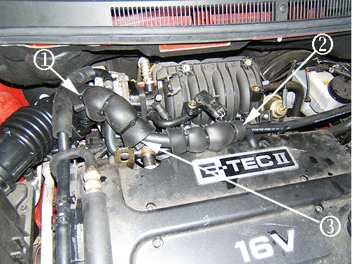
- Disconnect the IAT sensor connector from the air outlet duct assembly (1).
- Disconnect the coolant return hose from the throttle body assembly (1).
- Remove the MAP sensor assembly from the original mounting location (3) and save for use later in the procedure.
- Remove the throttle body assembly (1) and save.
- Remove the generator shackle bracket (1).
- Install the new generator shackle bracket (4), P/N 96892600, to the engine.
- Install the discarded throttle body nuts to an intake manifold stud bolt and tighten both nuts together (1).
- Unscrew the PCV valve from the cam cover and discard (1).
- Apply Teflon™ tape to the new PCV valve assembly (1), P/N 96942679. Install the new PCV valve into the cam cover, ensuring the PCV valve coolant pipes are in a horizontal plane (2).
- Install the new PCV valve hose (2) , P/N 96943257, to the new throttle body adapter (1), P/N 96875544, and then install the other end marked with white paint facing up to the PCV valve (2).
- Wrap the PCV valve hose to the throttle body adapter with foam insulator (1), P/N 96896827, size 60 mm x 100mm (2.4 in x 3.9 in) provided in the kit. Discard the two white tie-straps provided in the kit. The following P/N 12337820, tie-straps must be ordered from GMSPO. Use only two of the new tie-strap and retain the extra tie-straps for the next PCV Valve Kit to be installed.
- Install four new throttle body assembly bolts/screws, P/N 94500411, and the throttle body assembly to the new throttle body adapter (1).
- Connect the throttle body assembly harness connector (2)
- Remove the spring clamp and the upper radiator hose from the thermostat housing (2).
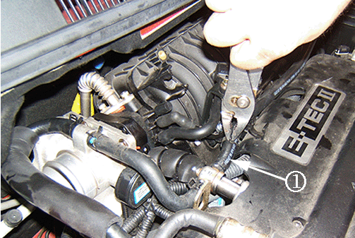
- Install the spring clamp with the new coolant inlet hose assembly, P/N 96887066, to the back or cowl side of the throttle body assembly (1). Make sure that the new coolant inlet hose assembly is positioned under the power steering hose (2).
- Removed in Step 5.5 was the PCV valve heater with attached hoses. The following hoses and spring clamps will need to be removed and re-used:
- Removed in Step 18.1 - Install the spring clamps with the short coolant inlet hose to the throttle body and the other end to the PCV valve (1).
- Remove the EVAP hose (3) from the intake manifold vacuum port (1) and from both retainers at the bottom of the intake manifold (2, 4).
- Remove the retainer from the stud bolt at the bottom lower left side of the intake manifold (1). Refer to Step 10 for the removal procedure of the stud bolt (1). Save the retainer for use later in the procedure.
- Install the new MAP sensor bracket (1), P/N 96891920, with a new bolt/screw, P/N 94500414, and the retainer (2) to the bottom of the intake manifold.
- Install the EVAP hose to the intake manifold vacuum port (4) and to both retainers at the bottom of the intake manifold (3).
- Install the MAP sensor (2) on the new MAP sensor bracket, P/N 96891920, with a new bolt/screw (1), P/N 94500414, and connect the MAP sensor wiring harness connector (3). The MAP sensor connector should be oriented at a 5 o’clock position relative to the intake manifold with the harness (3) positioned toward the front of the vehicle as shown above.
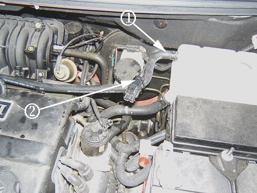
- Install the original spring clamp and coolant outlet hose removed in Step 18.2 to the new PCV valve assembly port (1).
- Install the original spring clamp and coolant outlet hose removed in Step 18.2 to the coolant surge tank (1). If equipped, install a new tie strap to the ABS test connector and attach it to the coolant return hose at the side of the coolant surge tank (2).
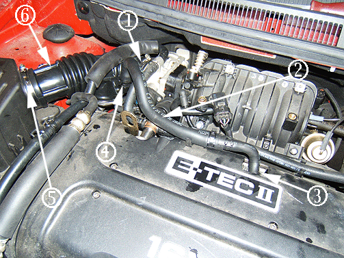
- Install the new air outlet duct assembly (6), P/N 96889507, to the throttle body (1). Install the other end to the air cleaner assembly (5).
- Wrap the breather hose and coolant outlet return hose together at the right side of the PCV valve with foam insulator (2), P/N 96942680, size 80 mm x 130 mm (3.1 in x 5.1 in) provided in the kit. Secure the insulator with three tie straps, P/N 94530232, also provided in the kit.
- Wrap the breather hose and coolant outlet return hose together at the left side of the PCV valve with foam insulator (3), P/N 96942681, size 130 mm x 145 mm (5.1 in x 5.7 in) provided in the kit. Secure the insulator with two tie straps, P/N 94530232, also provided in the kit.
- Top off the coolant and install the surge tank cap. Refer to the Cooling System Draining and Filling Procedure in SI .
- Connect the negative battery cable.
- Reset the radio stations and the clock.
- Perform the following idle relearn procedure:
- Reprogram the ECM with the new calibrations for the Throttle Body Icing Kit.
- Road test the vehicle with a Tech 2® scan tool connected.
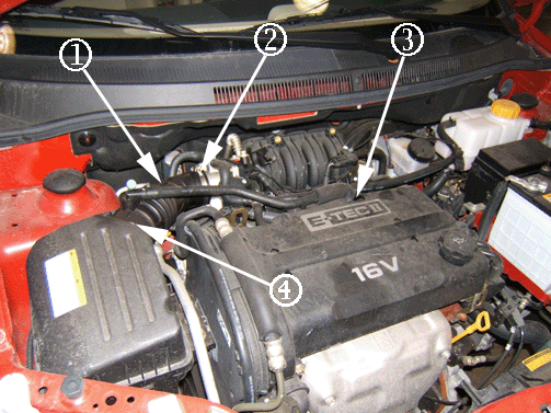
| 3.1. | Remove the clamp from the air outlet duct assembly at the throttle body (2). |
| 3.2. | Disconnect the breather tube at the cam cover (3). |
| 3.3. | Remove the clamp from the air outlet duct assembly at the air cleaner assembly (4). |
| 3.4. | Remove the air outlet duct assembly with the breather tube from the vehicle. |
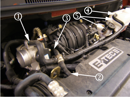
| 4.1. | Disconnect the PCV valve heater hose from the PCV Valve (2). |
| 4.2. | Disconnect the PCV valve heater hose from the intake manifold (3). |
| 4.3. | Disconnect the coolant return hose from the PCV valve heater to the coolant surge tank (4). |
| 4.4. | If equipped, remove the tie strap holding the ABS Test Connector to the coolant return hose at the side of the coolant surge tank (5). |
| 4.5. | Remove the PCV valve heater with attached hoses from the vehicle and save. The hoses will be used later in the procedure. |
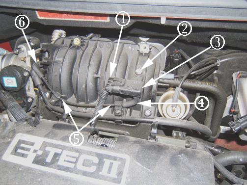
| 5.1. | Remove the MAP sensor engine harness connector (1). |
| 5.2. | Remove the MAP sensor bolt/screw from the intake manifold (2) and discard the fastener. |
| 5.3. | Remove the MAP sensor vacuum harness tube assembly from the vehicle and discard. Disconnect the vacuum harness at the intake manifold vacuum port (6) , two retainers at the bottom of the intake manifold (5) and at the MAP sensor (4). Discard the MAP sensor vacuum harness tube assembly . |
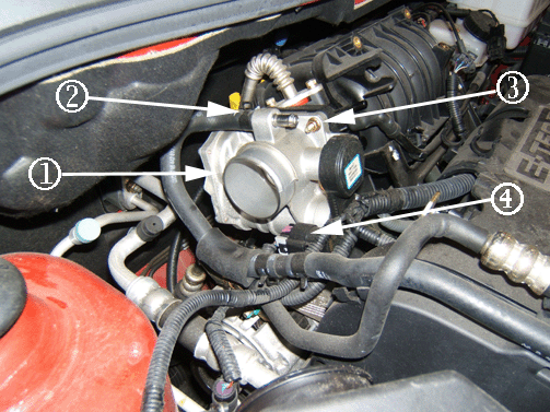
| 6.1. | Disconnect the throttle body assembly harness connector (4). |
| 6.2. | Disconnect the coolant hoses from the throttle body assembly (2). |
| 6.3. | Remove the four throttle body retaining bolts/nuts (3) and discard the fasteners. |
| 6.4. | Remove the throttle body. Leave the gasket attached to the intake manifold. |
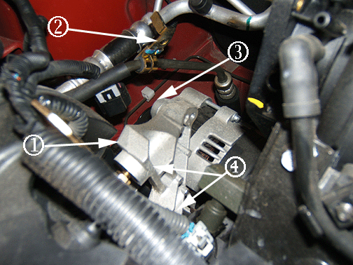
| 7.1. | Remove the power steering hose clamp nut. Then remove the clamp from the generator shackle bracket bolt (2). |
| 7.2. | Remove the generator shackle bracket bolt (3). |
| 7.3. | Remove the two nuts/washers holding the generator shackle bracket to the engine (4). |
| 7.4. | Remove the generator shackle bracket and discard bracket. Save all fasteners for use later in the procedure. |
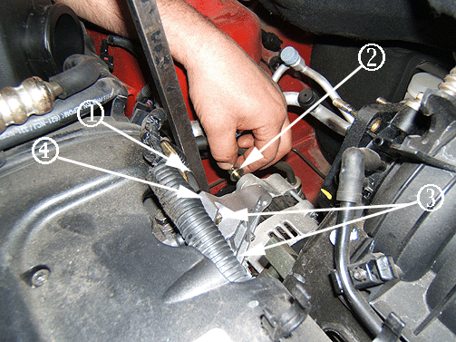
| 8.1. | Install the nuts and the washers holding the generator shackle bracket to the engine (3). |
Tighten
Tighten the generator shackle bracket nuts to 25 N·m(18 lb ft).
| 8.2. | Install the generator shackle bracket bolt by hand (2). Use a pry bar (1 ) and lightly pry against the generator to align and start the bolt by hand. |
Tighten
Tighten the generator shackle bracket bolt to 25 N·m(18 lb ft).
| 8.3. | Install the power steering hose clamp and nut to the generator shackle bracket bolt (2). |
Tighten
Tighten the nut to the generator shackle bracket bolt to 10 N·m(89 lb ft).
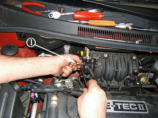
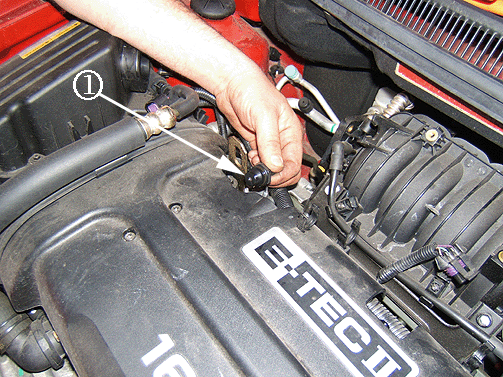
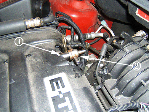
Once the nuts are jammed together, turn counterclockwise to remove the stud bolt. Repeat this process for the other stud bolts. Discard all removed stud bolts.
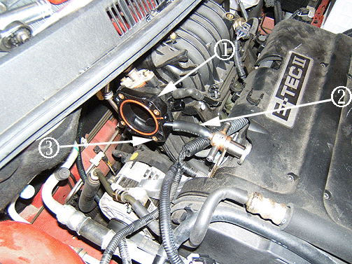
Install the new throttle body adapter with four new Allen head bolts/screws (3), P/N 94501639, to secure the throttle body adapter (1) to the intake manifold.
Tighten
Tighten the four Allen head throttle body adapter bolts/screws to 10-12 N·m (90 lb in).
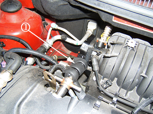
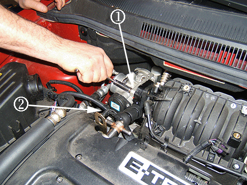
Tighten
Tighten the four throttle body assembly bolts/screws to the throttle body adapter to 10-12 N·m (90 lb in).
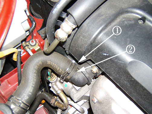
Important: Block the coolant hoses at the thermostat housing to prevent any leaks.
| 15.1. | Remove and discard the throttle body heater coolant inlet hose assembly from the thermostat housing (1) and connect a new throttle body heater coolant inlet hose assembly, P/N 96887066, to the thermostat housing by using a pair of long nose pliers to remove and install spring clamp. |
| 15.2. | Position the new coolant inlet hose assembly on top of the timing belt cover in place of the old one (1). |
| 15.3. | Install the spring clamp and the upper radiator hose to the thermostat housing (2) |
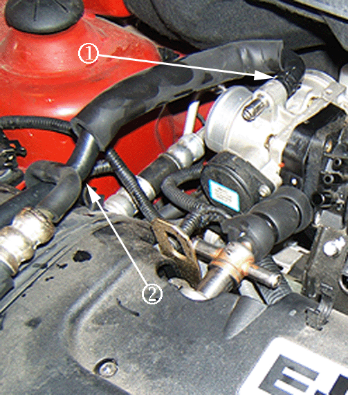
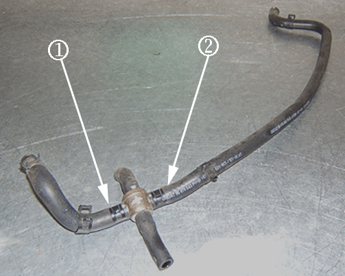
| 17.1. | Throttle body short coolant inlet hose to PCV valve (1). |
| 17.2. | PCV valve coolant outlet hose to the surge tank (2). |
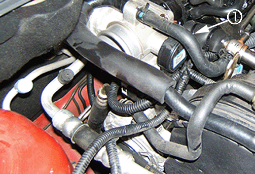
Important: The spring clamp to the PCV valve should be located with the spring towards the intake manifold to prevent damage to the breather hose.
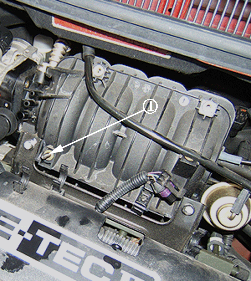
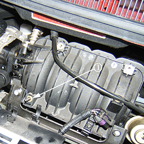
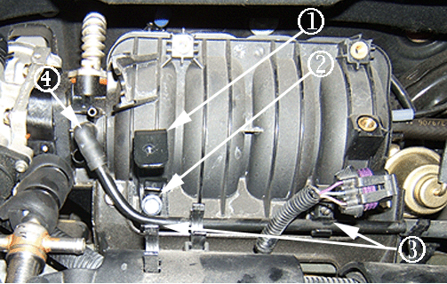
Important: Ensure that the retainer's larger slot is at the bottom of the intake manifold as shown (3).
Tighten
Tighten the MAP sensor bracket bolt/screw to 10-12 N·m (90 lb in).
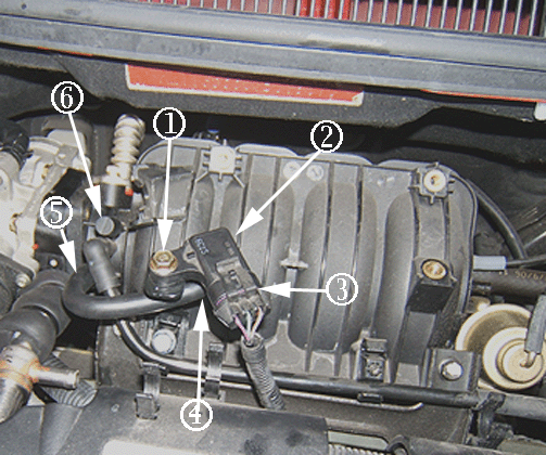
Important: The MAP sensor hose and bracket position (4) is critical. The hose should not contact the MAP sensor bracket. Refer to the illustration above.
Tighten
Tighten the MAP sensor bolt/screw (1) to 10-12 N·m (90 lb in).
| 21.1. | Install the MAP sensor vacuum tube assembly, P/N 96891970, between the lower port on the intake manifold (5) and to the underside of the MAP sensor (4). Ensure that the larger end of the vacuum tube assembly (5) is oriented toward the intake manifold vacuum port as shown above. |
| 21.2. | Install the intake manifold vacuum hole plug, P/N 96351328, on the remaining open intake manifold port (6) as shown above. |
Important: The spring clamp should be located with the spring towards the intake manifold to prevent damage to the breather hose.
| 24.1. | Tighten both clamps. |
Tighten
Tighten the air outlet duct assembly clamps to 3 N·m (27 lb in).
| 24.2. | Install the IAT sensor connector to the new air outlet duct assembly (6). |
| 24.3. | Install the new crankcase vent hose assembly (2), P/N 96896825, to the cam cover (3) and the other end to the new air outlet duct assembly (4). |
| 24.4. | Ensure that the new spring clamps are not in contact with any other hose or engine component. |
Important: It may be necessary to provide additional slack, by re-routing MAP sensor engine wiring harness so crankcase breather insulation will not pull on and cause damage to the wiring harness.
Important: A third tie strap may be needed to secure the insulator as shown above (1). Use one tie-strap P/N 12337820 if necessary.
Important: It may be necessary to re-route the crankcase breather hose and insulation, so it is not in contact with the engine lift hook bracket.
Important: Be sure to add the correct coolant to the vehicle's cooling system.
Tighten
Tighten the battery negative cable bolt to 4.5 N·m (40 lb in).
| 29.1. | Turn the ignition ON. |
| 29.2. | Turn the ignition OFF for 15 seconds. |
| 29.3. | Turn the ignition ON for 5 seconds. |
| 29.4. | Turn the ignition OFF for 15 seconds. |
| 29.5. | Start the engine in park/neutral. |
| 29.6. | Allow the engine to run until the engine coolant is above 85°C (185°F). |
| 29.7. | Turn the A/C ON for 10 seconds, if equipped. |
| 29.8. | If the vehicle is equipped with an automatic transaxle, apply the parking brake. While pressing the brake pedal, place the transaxle in D (drive) for 10 seconds. |
| 29.9. | Turn the A/C OFF for 10 seconds, if equipped. |
| 29.10. | If the vehicle is equipped with an automatic transaxle, while pressing the brake pedal, place the transaxle in park/neutral. |
| 29.11. | Turn the ignition OFF. The idle learn procedure is now complete. |
ECM Reprogramming Service Procedure
The calibration numbers required for this service procedure are programmed into control modules via a Techline Tech 2® scan tool and TIS2Web website with the following calibration updates:
Vehicle | ECM P/N | SW Description |
|---|---|---|
2006 Aveo/ Wave | 96950901 (M/T) | KMRU |
96950902 (A/T) | KMIU | |
2007 Aveo/ Wave | 96950903 (M/T) | KMSU |
96950904 (A/T) | KMJU | |
2008 Aveo/ Wave | 96940281 (M/T) | KMQU |
96940282 (A/T) | KMHU |
Use data version 12.5 for 2007 or later, available on TIS2Web. If you cannot access the calibration, call the Techline Customer Support Center and it will be provided.
Important: Due to the time requirements of programming a controller, it is recommended that an external power source be used to maintain system voltage. Stable battery voltage is critical during programming. Any fluctuation,
spiking, over-voltage or loss of voltage will interrupt programming. To ensure trouble-free programming, GM recommends using one of the following external power sources:
• A Midtronic PCS charger. • A fully charged 12V jumper or booster pack disconnected from the AC voltage supply.
The ignition switch must be in the proper position. The Tech 2® prompts you to turn ON the ignition with the engine OFF. DO NOT change the position of the ignition switch during the programming procedure unless instructed to do so.
Make certain all tool connections are secure, including the following components and circuits:
| • | The RS-232 communication cable port. |
| • | The connection at the data link connector (DLC). |
| • | The voltage supply circuits. |
DO NOT disturb the tool harnesses while programming. If an interruption occurs during the programming procedure, programming failure or control module damage may occur.
DO NOT turn OFF the ignition if the programming procedure is interrupted or unsuccessful. Ensure that all control module and DLC connections are secure and the TIS terminal operating software is up to date.
Refer to the appropriate service procedure in SI to Reprogram the Engine Control Module (ECM) Operating System and Calibration
Tech 2® Pass-Through Programming Instructions
- Select Chevrolet or Pontiac -- Daewoo.
- Enter VIN Number.
- Select Controller -- ECM.
- Select Transmission -- Manual/Automatic.
- Select Country of Registration -- North America.
- Refer to above chart for the correct calibration update. If the calibration numbers match, program the ECM.
| 6.1. | Calibration Remarks: Revised calibration for new PCV system regarding throttle body icing. |
| 6.2. | When programming is completed, record the programming number on the repair order. |
Parts Information
Part Number | Description | Qty |
|---|---|---|
96896823 | Kit, PCV Valve | 1 |
12337820 | Tie-Straps (Qty 10) | 2 |
Warranty Information
For vehicles repaired under warranty, use :
Labor Operation | Description | Labor Time |
|---|---|---|
J7921* | PCV Valve Kit for Throttle Body Icing | 0.9 hr |
Add | Engine Control Module (ECM) Reprogramming for Throttle Body Icing | 0.5 hr |
Idle Learn Procedure without A/C | 0.2 hr | |
Idle Learn Procedure with A/C | 0.3 hr | |
* This is a unique labor operation for bulletin use only. It will not be published in the Labor Time Guide. | ||
