For 1990-2009 cars only
Removal Procedure
- Disconnect the negative battery cable.
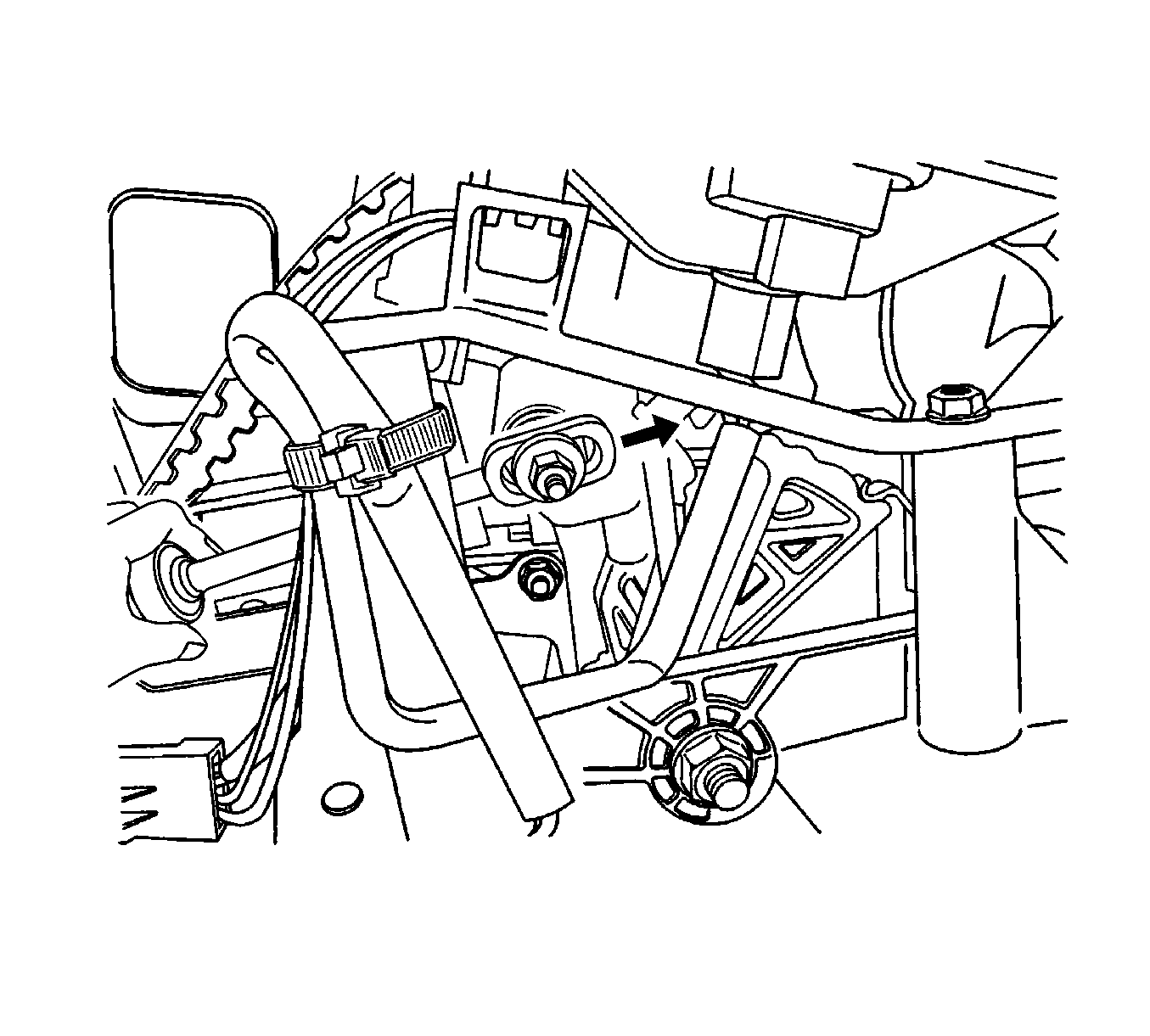
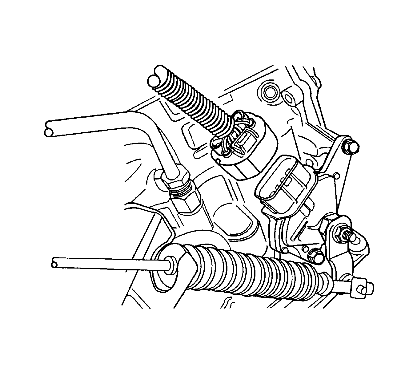
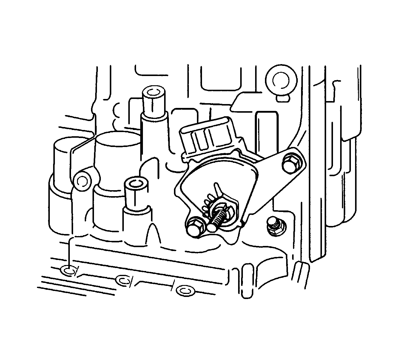
- Disconnect the park/neutral position (PNP) switch electrical connector from the wiring harness.
- Remove the E-ring.
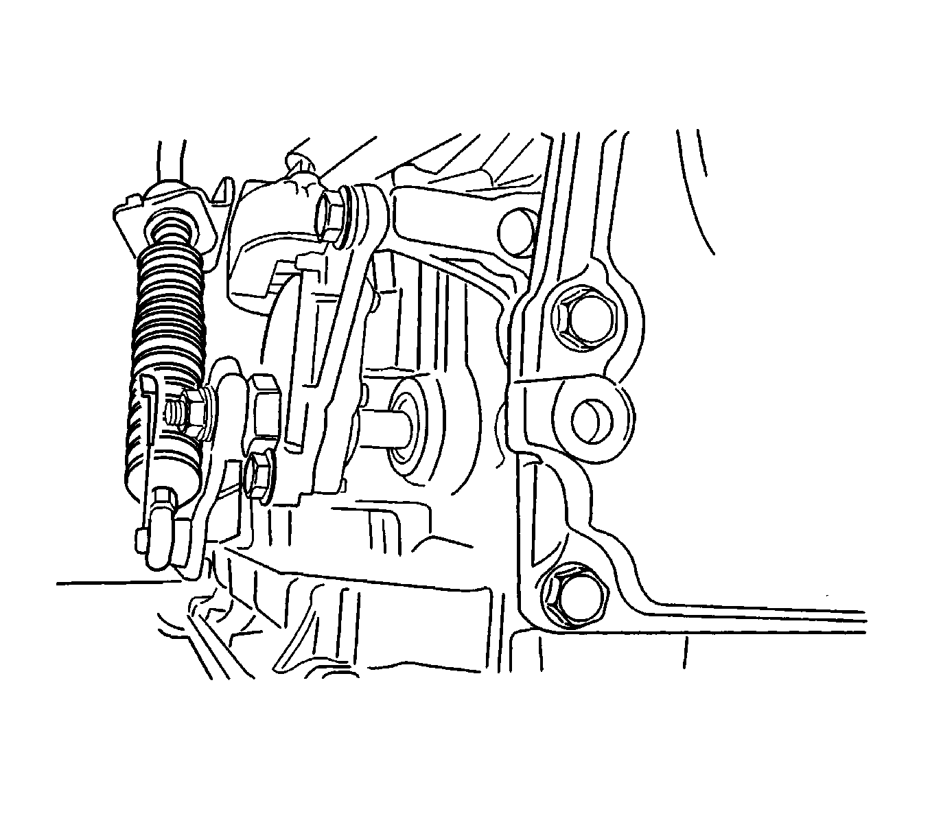
- Disconnect the shift control cable from the PNP switch lever.
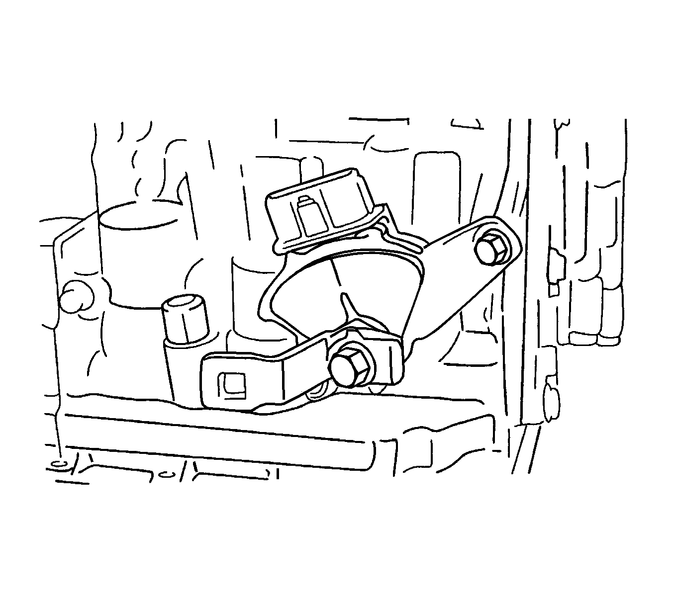
- Remove the retaining nut, the washer, and the control lever.
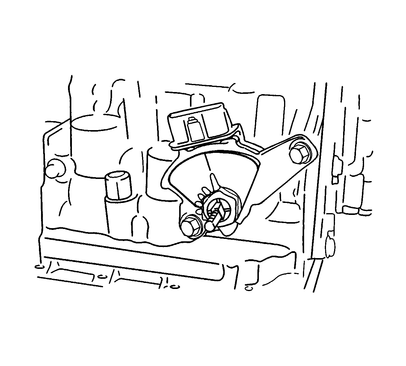
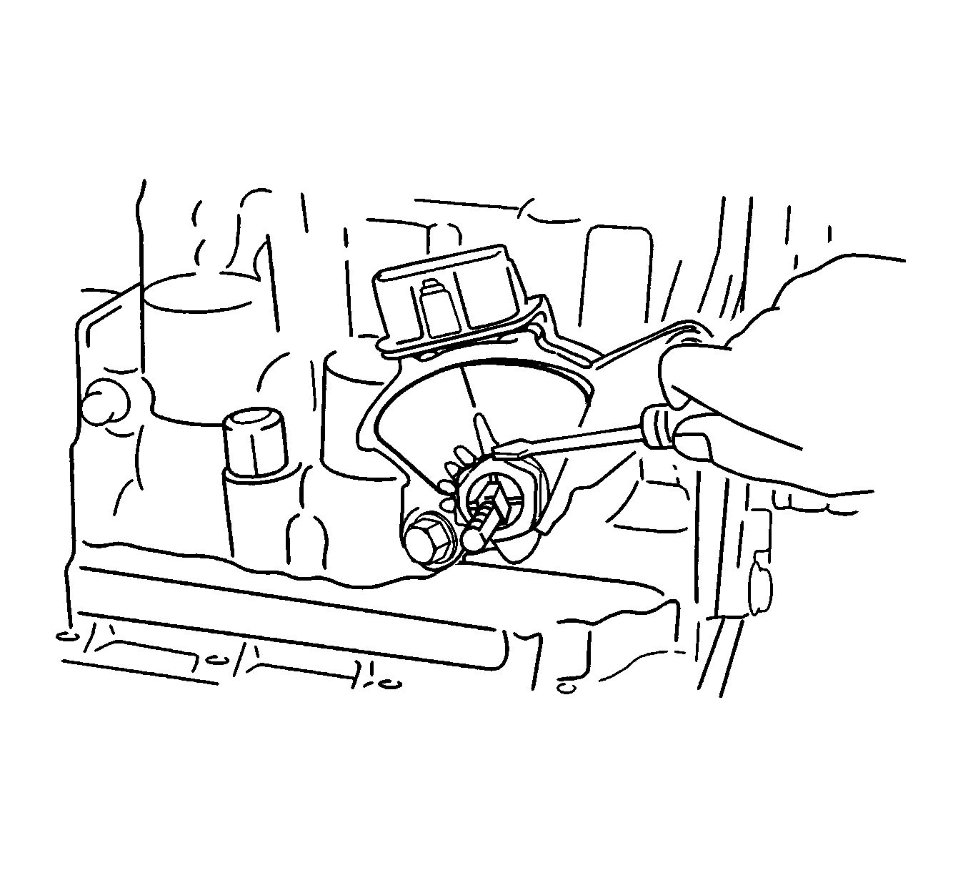
- Using a driver, unstake the lock washer and remove the nut.
Warning: Refer to Battery Disconnect Warning in the Preface section.
Installation Procedure
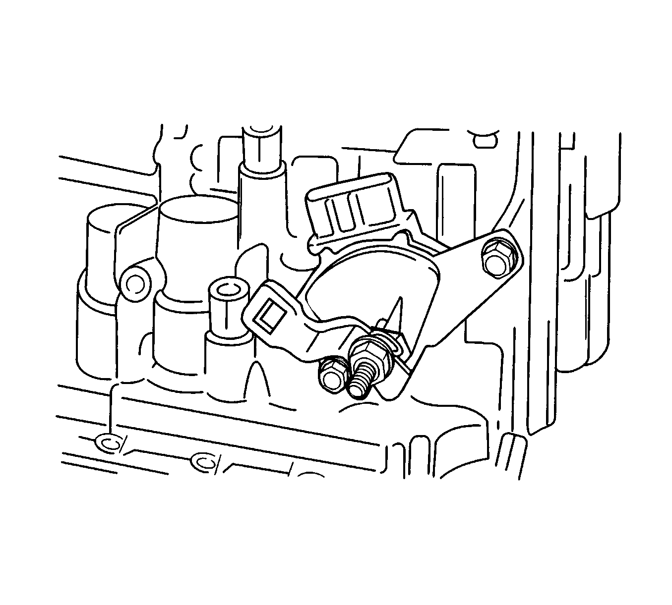
- Install the PNP switch onto the manual valve lever shaft and temporarily install the 2 adjusting bolts.
- Install the new lock washer and nuts and tighten to 12 N·m (106 lb in).
- Temporarily install the control lever
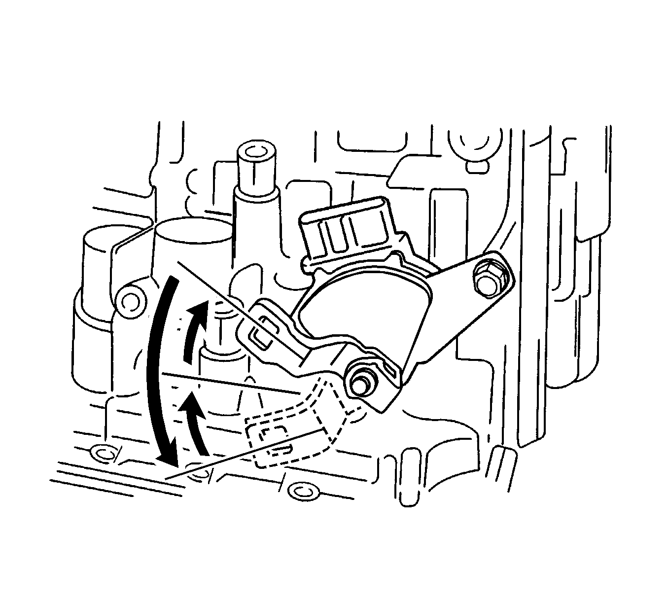
- Turn the lever counterclockwise until it stops, then turn it clockwise 2 notches.
- Remove the control lever.
- Align the groove with the neutral basic line, then install the bolts and tighten to 5 N·m (44 lb in).
- Using a screwdriver, stake the nut with the lock washer.
- Install the control lever, washer and nut and tighten to 12 N·m (106 lb in).
- Connect the control cable to PNP switch.
- Connect the PNP switch electrical connector.
- Adjust the control cable. Refer to Range Selector Lever Cable Adjustment.
- Install the control cable adjusting nut and tighten to 8 N·m (71 lb in).
- Connect the negative battery cable.
Caution: Refer to Fastener Caution in the Preface section.
