Removal Procedure
- Disconnect the negative battery cable.
- Remove the air intake duct.
- Remove the accelerator cable splash shield from accelerator cable bracket.
- Disconnect the accelerator, the cruise, and the transmission control cables.
- Remove the vacuum hose harness from top of the air inlet.
- Disconnect the crankcase ventilation valve and the power brake vacuum hoses from the vacuum tubes at the upper manifold (position vacuum hoses out of the way).
- Remove the electrical connectors at MAP sensor, TP sensor, and IAC valve.
- Remove the bolts/nuts attaching accelerator cable bracket (position bracket and cables out of the way).
- Remove the MAP sensor.
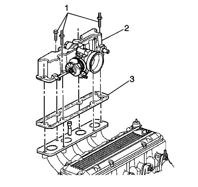
- Remove the bolts/studs (1) attaching upper manifold to the lower manifold (position fuel injector wiring harness out of the way).
- Remove the upper manifold assembly (2) and gasket (3) (discard gasket).
- Clean the gasket mating sufaces.
- Inspect the replacement upper manifold for items that are to be transferred to the new manifold.
- Disassemble the upper manifold following the component repair procedures.
- Assemble the replacement upper manifold with the transferred parts following the component repair procedures.

Notice: Use care when cleaning the old gasket from the aluminum surfaces in order to prevent damage to the sealing surfaces.
Installation Procedure
- Install the new upper manifold gasket (3).
- Install the upper manifold assembly (2) (reposition the injector wiring harness).
- Install the upper manifold attaching bolts/studs (1).
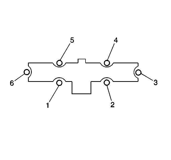
- Tighten the upper manifold bolts/studs to the tightening sequence shown.
- Install the MAP sensor.
- Install the accelerator cable bracket with attaching bolt/nuts.
- Install the accelerator, cruise, and transmission control cables.
- Install the splash shield to accelerator bracket.
- Install the electrical connectors to the MAP sensor, the TP sensor, the IAC valve, and the EGR vacuum solenoid.
- Install the vacuum hose harness to the top of the air inlet.
- Connect the crankcase ventilation valve and the power brake vacuum hoses to the vacuum tubes at the upper manifold.
- Install the air intake duct.
- Connect the negative battery cable.
Notice: The EVAP canister may have released carbon particles which caused this part to fail and may cause damage to other components. Check the EVAP canister for loose carbon before returning the vehicle to service.


Tighten
Tighten the upper manifold bolts/studs to 30 N·m (22 lb ft).
Refer to tightening sequence.
Notice: Use the correct fastener in the correct location. Replacement fasteners must be the correct part number for that application. Fasteners requiring replacement or fasteners requiring the use of thread locking compound or sealant are identified in the service procedure. Do not use paints, lubricants, or corrosion inhibitors on fasteners or fastener joint surfaces unless specified. These coatings affect fastener torque and joint clamping force and may damage the fastener. Use the correct tightening sequence and specifications when installing fasteners in order to avoid damage to parts and systems.

Tighten
| • | Tighten the accelerator cable bracket nut to 30 N·m (22 lb ft). |
| • | Tighten the accelerator cable bracket bolts to 25 N·m (18 lb ft). |
Tighten
Tighten the accelerator cable splash shield screws to 1.9 N·m(17
lb in).
Removal Procedure
- Relieve fuel system pressure. Refer to theFuel Pressure Relief Procedure
- Disconnect the negative battery cable.
- Remove the upper manifold assembly.
- Remove the quick-connect fittings at the engine compartment fuel feed and return pipes.
- Use compressed air in order to blow out dirt from all quick-connect fittings before removal.
- Grasp both ends of one fuel pipe connection and twist 1/4 turn in each direction in order to loosen any dirt in quick-connect fitting. Repeat this process for the other fitting.
- Choose the correct tool from J 37088-A tool set for size of fitting.
- Insert the tool into the female connector. Push inward in order to release the male connector.
- Repeat for the other fitting.
- Remove the plug fuel feed and return pipes as required.
- Remove the bolts retaining the power steering pump brace, and brace.
- Remove the engine fuel inlet pipe retainer nuts and retainers.
- Remove the fuel inlet pipe and seal.
- Remove the transmission fill tube attaching nut.
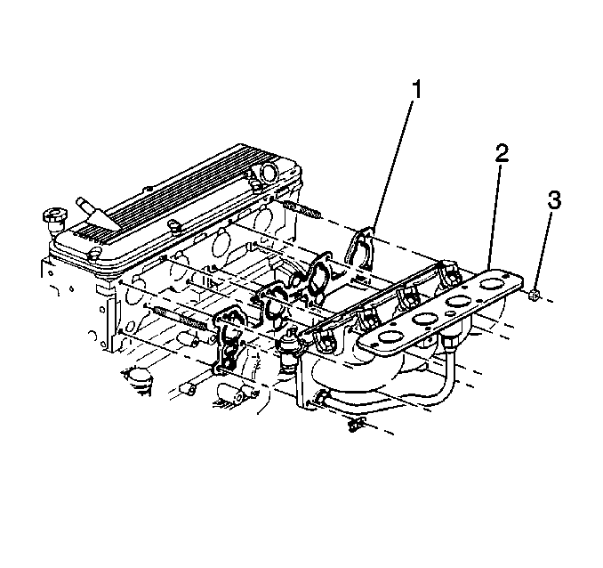
- Remove the lower manifold attaching nuts (3).
- Remove the lower manifold (2). Discard gasket (1)
- Whenever it is necessary to remove rust or burrs from the male tube end of the fuel feed/return pipes quick-connect fittings, use emery cloth in a circular motion with the tube end to prevent damage to O-ring sealing surface.
- Remove the gasket mating surfaces.
- Using a clean shop towel in order to wipe off the male tube end of the fuel feed/return pipes quick-connect fittings. Replace the pipes if damaged.
- Inspect the lower manifold for items that are to be transferred to the new manifold.
- Disassemble the lower manifold and other remaining parts to be transferred following component repair procedures.
- Assemble the replacement lower manifold with the transferred parts following the component repair procedures.

Notice: Use care when cleaning the old gasket from the aluminum surfaces in order to prevent damage to the sealing surfaces.
Installation Procedure
- Install the new lower manifold gasket (1).
- Position the lower manifold (2) on the studs.
- Install the fuel inlet pipe retaining nut.
- Install the fuel pipe support nut.
- Install the lower manifold attaching nuts (3).
- Install the transmission fill tube attaching nut.
- Install the new fuel inlet pipe O-ring seal.
- Install the fuel inlet pipe nut (Finger tighten only).
- Support the nut on the bottom of the lower manifold (Finger tighten only).
- Install the power steering pump brace with the attaching bolts.
- Unplug the fuel feed and the return pipes.
- Install the fuel feed and the return line quick-connect fittings
- Install the upper manifold assembly.
- Tighten the fuel filler cap.
- Connect the negative battery cable.
- Inspect for leaks.

Tighten
Tighten the fuel inlet pipe retaining nut to 30 N·m (22 lb ft).
Notice: Use the correct fastener in the correct location. Replacement fasteners must be the correct part number for that application. Fasteners requiring replacement or fasteners requiring the use of thread locking compound or sealant are identified in the service procedure. Do not use paints, lubricants, or corrosion inhibitors on fasteners or fastener joint surfaces unless specified. These coatings affect fastener torque and joint clamping force and may damage the fastener. Use the correct tightening sequence and specifications when installing fasteners in order to avoid damage to parts and systems.
Tighten
Tighten the fuel pipe support nut to 10 N·m (89 lb in).

Tighten
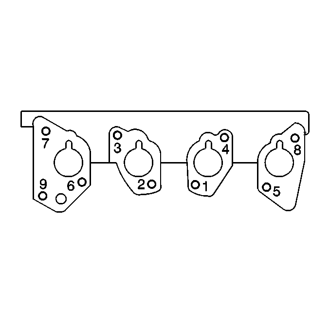
Tighten the lower manifold attaching nuts 30.0 N·m (22 lb ft),
using tightening sequence.

Caution: Always apply a few drops of clean engine oil to the male pipe ends before connecting the fuel pipe fittings in order to reduce the risk of fire and personal injury. This will ensure proper reconnection and prevent a possible fuel leak. During normal operation, the O-rings located in the female connector will swell and may prevent proper reconnection if not lubricated.
Important:
• Apply a few drops of clean engine oil to the male tube ends of
the engine fuel feed and the return pipes. • Push the connectors together in order to cause the retaining tabs/fingers
in order to snap into place. • Once installed, pull on both ends of each connection in order
to ensure that they are secure. • Repeat for the other fitting.
| 16.1. | Turn the ignition switch ON for 2 seconds. |
| 16.2. | Turn the ignition switch OFF for 10 seconds. |
| 16.3. | Turn the ignition switch ON. |
| 16.4. | Check for fuel leaks. |
