Front Caster and Camber Adjustment RWD
Important: Before you adjust caster and camber angles, raise and release the front bumper. Do this twice in order to allow the vehicle to return to a normal height. Refer to Wheel Alignment Specifications .
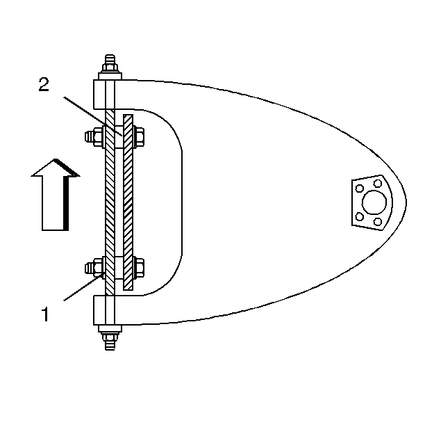
- Adjust the caster and the camber by inserting shims between the upper control arm shaft and the frame bracket. Add shims or subtract shims or transfer shims in order to change the readings.
- In order to adjust the caster and the camber, loosen the upper control arm shaft-to-frame nuts (1). Add shims or remove shims (2) as required. Tighten the nuts. Check the toe after you change the caster and the camber.
- Caster--Transfer the shims from front to rear or from rear to front. The transfer of one shim from the rear bolt to the front bolt decreases positive caster.
- Camber--Change the shims at the front and the rear of the cross shaft. Add an equal number of shims at the front and the rear of the cross shaft. This decreases positive camber.
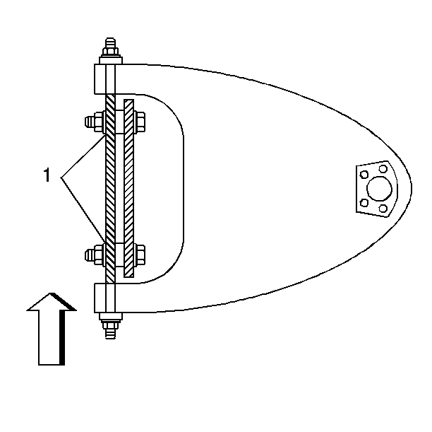
- A normal shim pack will leave at least two threads of the bolt exposed beyond the nut (1). The difference between the front shim pack and the rear shim pack must not exceed 10 mm (0.40 in). If you cannot meet these requirements, check for damage to the control arms and to related parts.
- Tighten the nut on the thinner shim pack first. This improves the shaft-to-frame clamping force. This also improves torque retention.


Notice: Refer to Fastener Notice in the Preface section.
Tighten
Tighten the nuts to 75 N·m (55 lb ft).
Front Caster and Camber Adjustment 4WD
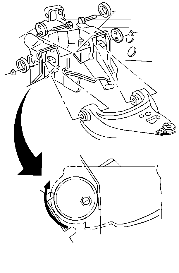
- Use the cams on the upper control arm frame attaching bolts to adjust the caster and the camber.
- Tighten the nuts after you select the proper cam position.

Important: Before adjusting the caster angle and camber angle, raise and release the front bumper. Do this twice in order to allow the vehicle to return to a normal height. Refer to Wheel Alignment Specifications .
To adjust the caster and the camber, loosen the upper control arm-to-frame attaching nuts. Rotate the cam by rotating the bolt head.
| • | Caster--To increase positive caster, move the front cam lobe inboard and move the rear cam lobe outboard. |
| • | Camber--To increase positive camber, move the front and the rear cam lobes inboard. |
Notice: Use the correct fastener in the correct location. Replacement fasteners must be the correct part number for that application. Fasteners requiring replacement or fasteners requiring the use of thread locking compound or sealant are identified in the service procedure. Do not use paints, lubricants, or corrosion inhibitors on fasteners or fastener joint surfaces unless specified. These coatings affect fastener torque and joint clamping force and may damage the fastener. Use the correct tightening sequence and specifications when installing fasteners in order to avoid damage to parts and systems.
Tighten
Tighten the nuts to 115 N·m (85 lb ft).
