Tools Required
| • | J 8092 Universal Driver Handle |
| • | J 36660-A Electronic Torque Angle Meter |
| • | J 36996 Balance Shaft Installer |
Removal Procedure
- Remove the radiator. Refer to Radiator Replacement in Engine Cooling.
- Remove the A/C condenser. Refer to Condenser Replacement in Heating, Ventilation and Air Conditioning.
- Remove the valve lifter pushrod guide. Refer to Valve Lifter Replacement .
- Remove the timing chain and camshaft sprockets. Refer to Timing Chain and Sprocket Replacement .
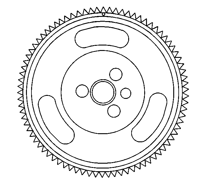
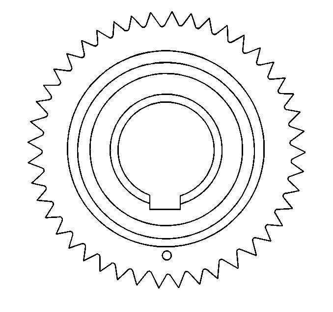
- Remove the balance shaft drive gear.
- Remove the balance shaft driven gear bolt from the balance shaft.
- Remove the balance shaft driven gear from the balance shaft.
- Remove the bolts and the balance shaft retainer.
- Use a soft-faced hammer in order to remove the balance shaft from the engine block.
- Clean and inspect the balance shaft. Refer to Balance Shaft Cleaning and Inspection .
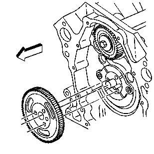
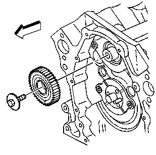
Important: The balance shaft drive and balance shaft driven gears are serviced as a set. The set includes the balance shaft driven gear bolt.
| 6.1. | Use a wrench in order to secure the balance shaft. |
Place the wrench onto the balance shaft near to the balance shaft front bearing.
| 6.2. | Remove the balance shaft bolt. |
| 6.3. | Remove the wrench from the balance shaft. |
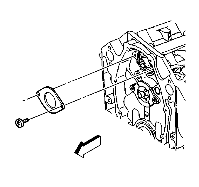
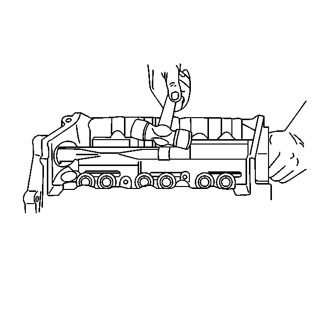
Important: The balance shaft and the balance shaft front bearing are serviced only as a package. Do not remove the balance shaft front bearing from the balance shaft.
Installation Procedure
- Apply clean engine oil GM P/N 12345610 (Canadian P/N 993193) or equivalent to the balance shaft front bearing.
- Use the J 36996 and the J 8092 in order to install the balance shaft.
- Install the balance shaft retainer and bolts.
- Install the balance shaft driven gear onto the balance shaft.
- If reusing the fastener, apply threadlock GM P/N 12345382 (Canadian P/N 10953489) or equivalent to the threads of the balance shaft driven gear bolt.
- Install the balance shaft driven gear bolt.
- Remove the wrench from the balance shaft.
- Rotate the balance shaft by hand in order to ensure that there is clearance between the balance shaft and the valve lifter pushrod guide. If the balance shaft does not rotate freely, check to ensure that the retaining ring on the balance shaft front bearing is seated on the case.
- Install the balance shaft drive gear. DO NOT install the camshaft sprocket bolts at this time.
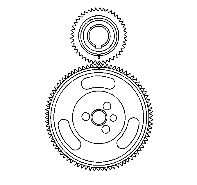
- Rotate the engine camshaft so that the timing mark on the balance shaft drive gear is in the 12 o'clock position.
- Remove the balance shaft drive gear.
- Rotate the balance shaft so that the timing mark on the balance shaft driven gear is in the 6 o'clock position.
- Position the balance shaft drive gear onto the engine camshaft.
- Look to ensure that the balance shaft drive gear and the balance shaft driven gear timing marks are aligned.
- Install the timing chain and the camshaft sprocket. Refer to Timing Chain and Sprocket Replacement .
- Install the engine front cover. Refer to Engine Front Cover Replacement .
- Install the valve lifter pushrod guide. Refer to Valve Lifter Replacement .
- Install the A/C condenser. Refer to Condenser Replacement in Heating, Ventilation and Air Conditioning.
- Install the radiator. Refer to Radiator Replacement in Engine Cooling.
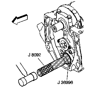
Important: The balance shaft and the balance shaft front bearing are serviced only as an assembly. Do not remove the balance shaft front bearing from the balance shaft.

Notice: Use the correct fastener in the correct location. Replacement fasteners must be the correct part number for that application. Fasteners requiring replacement or fasteners requiring the use of thread locking compound or sealant are identified in the service procedure. Do not use paints, lubricants, or corrosion inhibitors on fasteners or fastener joint surfaces unless specified. These coatings affect fastener torque and joint clamping force and may damage the fastener. Use the correct tightening sequence and specifications when installing fasteners in order to avoid damage to parts and systems.
Tighten
Tighten the bolts to 12 N·m (106 lb in).

| 6.1. | Use a wrench to secure the balance shaft. |
Place the wrench onto the balance shaft near to the balance shaft front bearing.
| 6.2. | Install the balance shaft driven gear bolt. |
Tighten
Tighten the balance shaft driven gear bolt to 20 N·m (15 lb ft).
Using the J 36660-A
rotate the
balance shaft driven gear bolt an additional 35 degrees.

