Removal Procedure
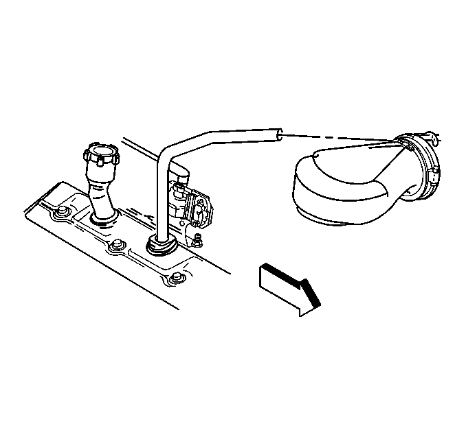
- Disconnect the breather tube at the air cleaner outlet duct.
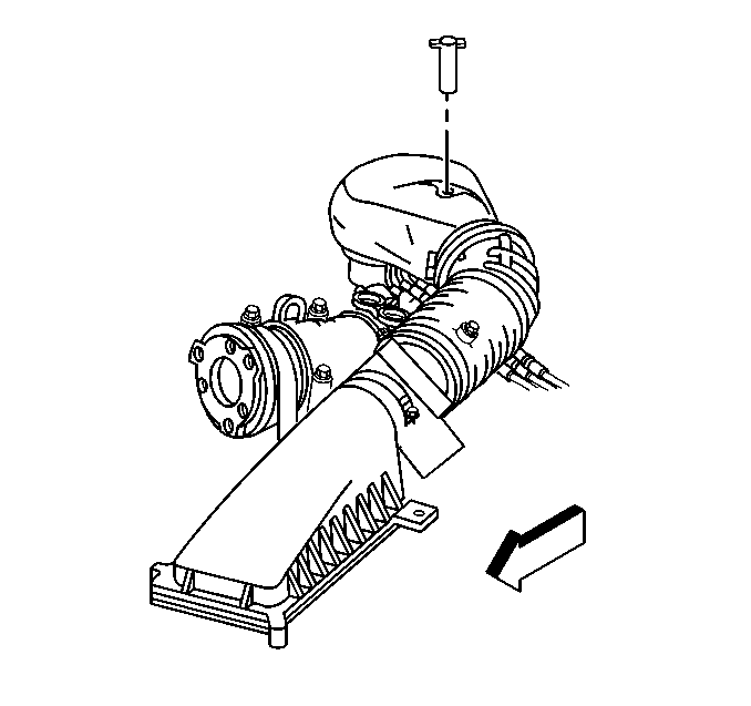
- Remove the air cleaner outlet duct retaining wingnut.
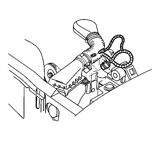
- Disconnect the IAT sensor harness connector.
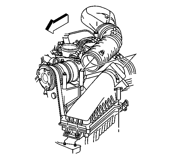
- Remove the air cleaner outlet duct from the throttle body.
- Remove the intermediate steering shaft. Refer to Lower Intermediate Steering Shaft Replacement in Steering Wheel and Column.
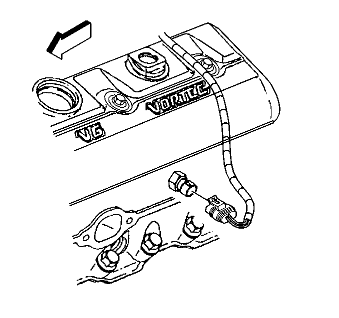
- Disconnect the engine coolant temperature (ECT) sensor electrical connector.
- Remove the radiator inlet hose support bracket and nut.
- Raise the vehicle. Refer to Lifting and Jacking the Vehicle in General Information.
- Disconnect the exhaust pipe from the exhaust manifold. Refer to Exhaust Manifold Pipe Replacement .
- Lower vehicle.
- Remove the front tire to gain access to the rear exhaust manifold bolts. Refer to Tire and Wheel Removal and Installation in Tires and Wheels.
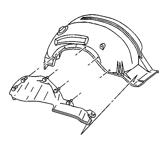
- Remove the fender wheelhouse extension.
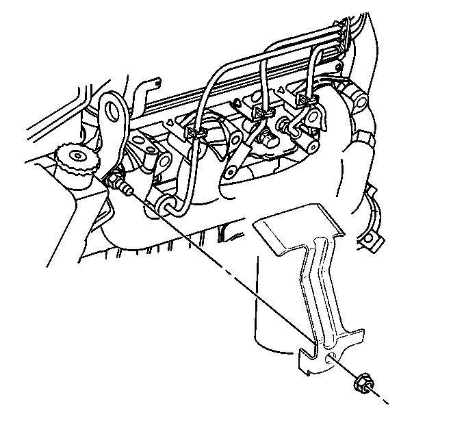
- Working through the wheel house opening disconnect the spark plug wires from the spark plugs.
- Remove the exhaust manifold bolts and the stud.
- Lower the vehicle.
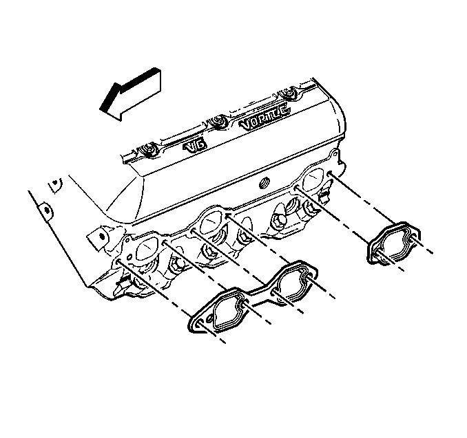
- From under the hood remove the exhaust manifold and the spark plug wire shields from the engine.
- Remove and discard the exhaust manifold gaskets.
- Clean all gasket surfaces. Refer to Exhaust Manifold Cleaning and Inspection in Engine Mechanical - 4.3L Unit Repair.
| 13.1. | Rotate the spark plug wire boot one half turn. |
| 13.2. | Pull outward on the spark plug wire boot to release from the spark plug. |
Installation Procedure
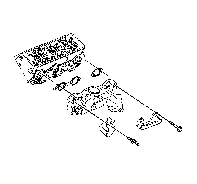
- Sub-assemble the bolts, spark plug wire shields, and NEW gaskets to the exhaust manifold.
- Ensure that the exhaust manifold bolts are held in place by the tabs on the exhaust manifold gaskets.
- From under the hood position the exhaust manifold by the engine.
- Raise the vehicle to the proper height.
- Working the wheelhouse opening, install the exhaust manifold.
- Install the spark plug wire shields.
- If reusing the fasteners, apply threadlock GM P/N 12345493 (Canadian P/N 10953488) or equivalent to the threads of the exhaust manifold bolts and stud.
- Install the exhaust manifold bolts and stud.
- Tighten the exhaust manifold bolts and stud on the first pass to 15 N·m (11 lb ft).
- Tighten the exhaust manifold bolts and stud on the final pass to 30 N·m (22 lb ft).
- Install the spark plug wires to the spark plug wire retainers.
- Install the spark plug wires onto the spark plugs.
- Install the fender wheelhouse extension.
- Install the front tire to. Refer to Tire and Wheel Removal and Installation in Tires and Wheels.
- Raise the vehicle. Refer to Lifting and Jacking the Vehicle in General Information.
- Connect the exhaust pipe to the exhaust manifold. Refer to Exhaust Manifold Pipe Replacement .
- Lower the vehicle.
- Connect the ECT sensor electrical connector.
- Install the radiator inlet hose support bracket and nut.
- Install the intermediate steering shaft. Refer to Lower Intermediate Steering Shaft Replacement in Steering Wheel and Column.
- Install air cleaner outlet duct to throttle body.
- Install air cleaner outlet duct to MAF sensor.
- Connect the IAT sensor harness connector.
- Install the air cleaner outlet duct retaining wingnut.
- Connect the breather tube to the air cleaner outlet duct.
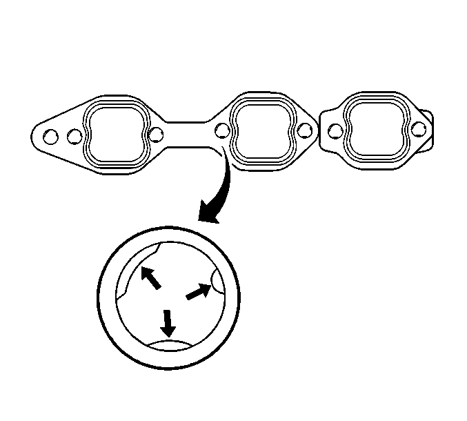
Important: To assist in installing the exhaust manifold to the engine, the tabs on a NEW exhaust manifold gasket will hold the gasket and bolts in place.
The stud installs in the front hole.
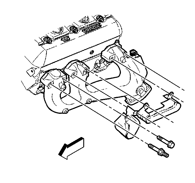
Notice: Use the correct fastener in the correct location. Replacement fasteners must be the correct part number for that application. Fasteners requiring replacement or fasteners requiring the use of thread locking compound or sealant are identified in the service procedure. Do not use paints, lubricants, or corrosion inhibitors on fasteners or fastener joint surfaces unless specified. These coatings affect fastener torque and joint clamping force and may damage the fastener. Use the correct tightening sequence and specifications when installing fasteners in order to avoid damage to parts and systems.
Tighten


Tighten
Tighten the radiator inlet hose support bracket nut to 36 N·m (27 lb ft).
Notice:
• Handle the MAF sensor carefully. • Do not drop the MAF sensor in order to prevent damage to the MAF
sensor. • Do not damage the screen located on the air inlet
end of the MAF. • Do not touch the sensing elements. • Do not allow solvents and lubricants to come in contact with the
sensing elements. • Use a small amount of a soap based solution in order to aid in
the installation.


