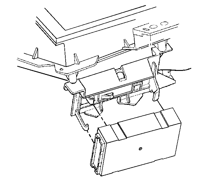
For 1990-2009 cars only
Removal Procedure
- Remove the left instrument panel (I/P) sound insulator from the vehicle. Refer to Instrument Panel Insulator Panel Replacement - Left Side .
- Remove the lower I/P sound insulator from the vehicle. Refer to Instrument Panel Insulator Panel Replacement .
- Disconnect the electrical connectors from the BCM.
- Bend the 2 snap retainers back slightly and pull the BCM from the bracket at an angle.

Important: The ignition switch should be in the OFF position when connecting or disconnecting the connectors to the body control module (BCM). Always disconnect the Brown BCM connector FIRST and connect the Brown BCM connector LAST. The BCM can set DTCs with the ignition switch in the OFF position.
Installation Procedure
- Install the BCM to the bracket at an angle under the wide hook retainer, with the label facing away from the bracket.
- Apply pressure on the left side of the BCM in order to move the module toward the mounting bracket base. Snap the module into place.
- Ensure that the module is fully seated. Ensure that both snap retainers are holding the module.
- Connect the electrical connectors to the BCM. Connect the brown connector LAST.
- Install the lower I/P sound insulator to the vehicle. Refer to Instrument Panel Insulator Panel Replacement .
- Install the left I/P sound insulator to the vehicle. Refer to Instrument Panel Insulator Panel Replacement - Left Side .
- Use the following components in order to program the BCM with the proper calibrations:
- Perform the BCM programming. Refer to Body Control Module (BCM) Programming/RPO Configuration .
- Clear the DTCs.
- Refer to Control Module References for programming and setup information.

| • | The Techline Terminal |
| • | The scan tool |
