4.3L Clutch
The 4.3L clutch system is described as the following:
| • | Size - 280 mm (11 in) |
| • | Clutch pressure plate - Diaphragm spring plate, non-self adjusting |
| • | Clutch disc - Damper spring style |
| • | Hydraulic system |
Clutch System Components
Clutch Pedal
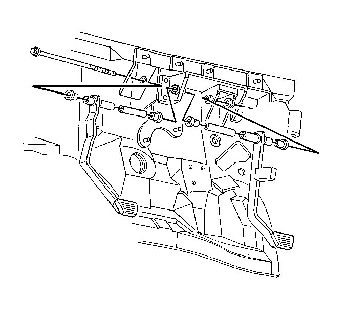
The clutch pedal, mounted on the engine cowl, is designed to compress the clutch hydraulic fluid with little driver effort. The pedal swivels on bushings. The clutch master cylinder pushrod connects to a pin on the pedal. A spring, located inside of the clutch master cylinder, returns the pedal to the correct position after depressing.
Clutch Master Cylinder
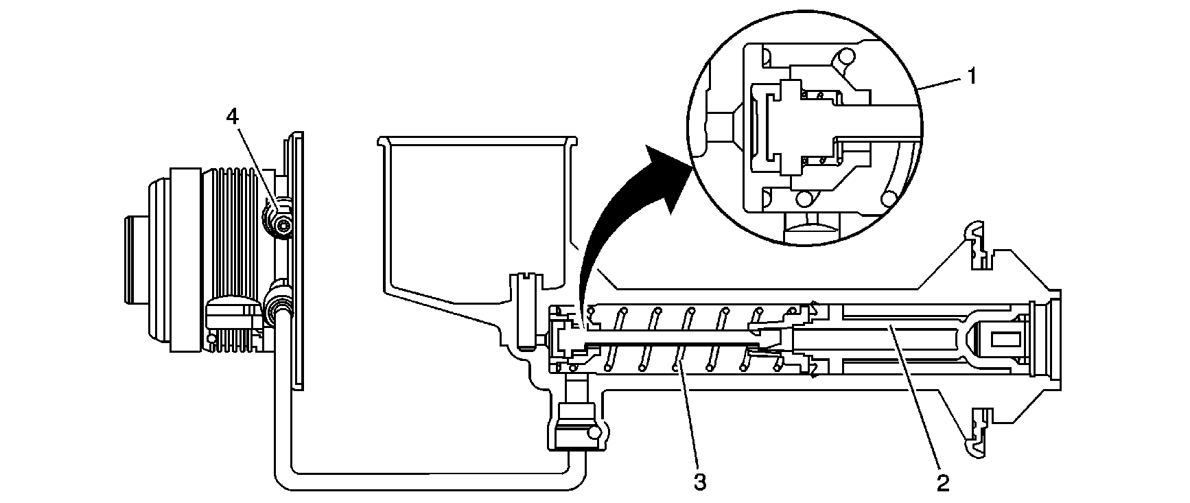
The reservoir, which is part of the master cylinder, supplies the fluid at the front of the master cylinder through the center feed port (1). The center feed port allows the flow of fluid from the reservoir to the cylinder when the pedal is in the complete returned position. The master cylinder uses a spring (3) to return the piston (2) to the clutch engagement position. When the clutch pedal is depressed, the piston moves forward in the cylinder, compressing the fluid. The compressed fluid travels through a hose to the clutch actuator cylinder. A bleeder screw (4) is located at the clutch actuator cylinder for bleeding the hydraulic system.
Clutch Actuator Cylinder and Release Bearing
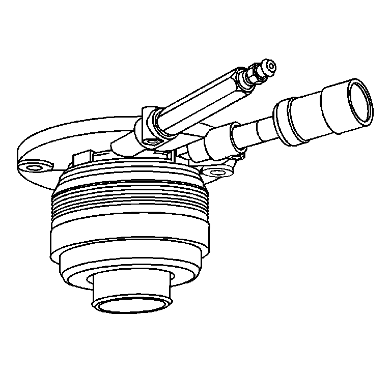
The clutch actuator cylinder is fastened to the front of the transmission. The actuator cylinder moves the clutch release bearing forward from the pressurized hydraulic fluid. The actuator cylinder has a piston, which has seals that slide on the housing assembly. There is a spring between the piston and housing to keep the piston at the extended position, so that the release bearing is in constant contact with the pressure plate fingers. The piston, or release bearing in the clutch actuator cylinder, moves towards the transmission as the clutch wears. The piston is at the furthest position from the transmission, with a new clutch. The clutch actuator has a bleeder for bleeding air out of the hydraulic system.
The release bearing is attached to the control actuator cylinder, which is attached to the front of the transmission. Movement of the clutch actuator cylinder piston, moves the release bearing, to press against the tips of the diaphragm spring fingers. Ball bearings, in the release bearing, enable it to turn while applying pressure to the fingers. Angular-contact bearings, found in hydraulic release systems, are in constant contact with the diaphragm spring fingers.
Pressure Plate Assembly
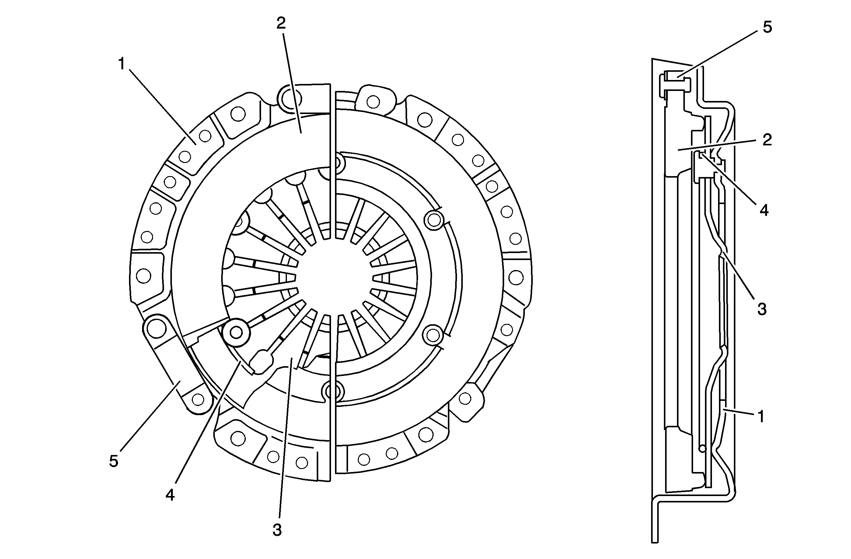
The diaphragm spring clutch consists of a pressure plate (2), a diaphragm spring (3), a pivot ring (4), drive straps (5), and a cover (1). When the release bearing contacts the tips of the diaphragm spring fingers, it moves them toward the flywheel. The outside diameter of the diaphragm spring pivots on a pivot ring inside the cover. This action lifts the pressure plate off the flywheel through the drive straps, which connect the cover to the pressure plate. As the clutch wears, there is an increase in pedal effort.
Clutch Disc
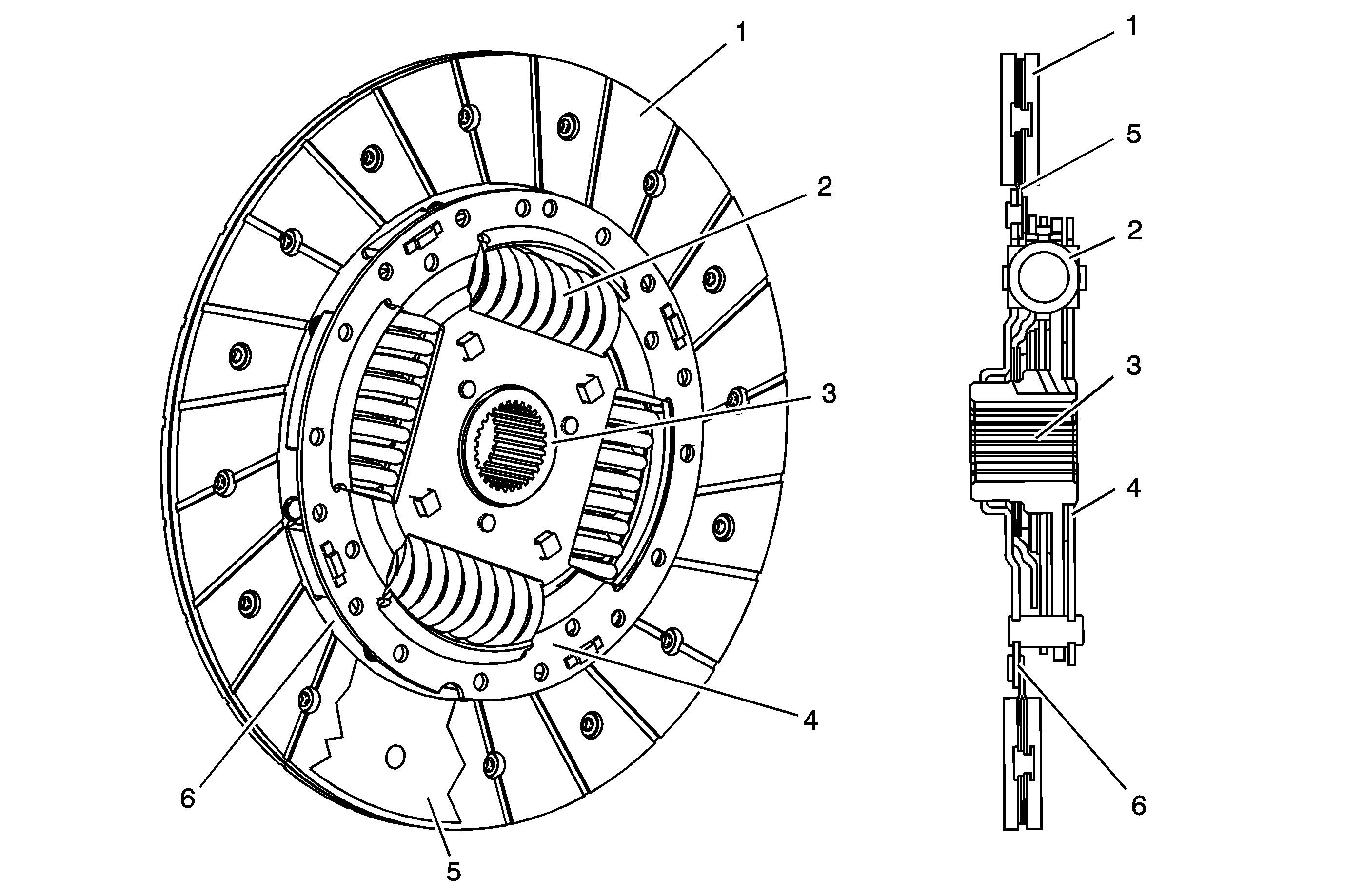
The clutch disc or driven member is a critical component in the service life of the clutch system. The disc provides smooth engagement and dampens engine vibrations. Mounted to the transmission input shaft, between the flywheel and the clutch pressure plate, the disc slides on the input shaft forward and backward. The disc is splined to the input shaft and cannot rotate without rotating the input shaft. The critical parts of the clutch disc are the hub flange (3) and the torsion springs (2). The hub flange (3) is located between the cover plate (4) and a retainer plate (6) and splined to fit the input shaft. The torsion springs (2), in the damper assembly, smooth the engagement and dampen vibrations. Friction material (1) is riveted to numerous components, called marcels, or cushion segments (5). Waves in marcels soften engagement.
Flywheel
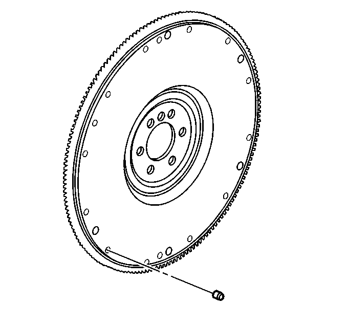
Bolted to the end of the crankshaft, the flywheel provides the mounting surface for the clutch. During engagement, the disc is clamped against the flywheel by the pressure plate. The flywheel acts as a heat sink, dissipating heat and moving it away from the clutch pressure plate and disc friction material. The flywheel must provide a smooth, flat surface in order for the clutch to operate properly.
Pilot Bearing/Bushing
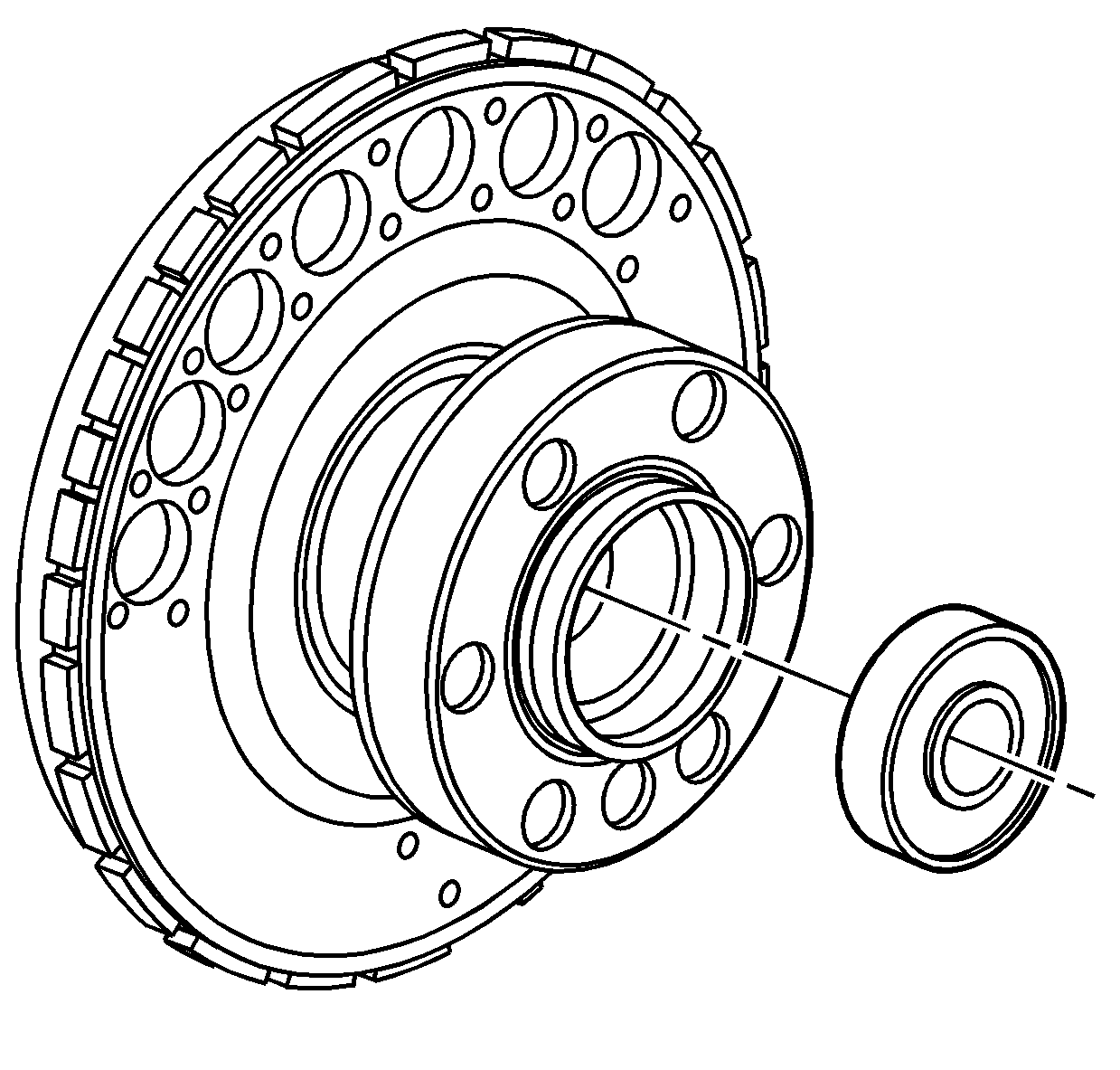
A pilot bearing, or bushing, is located in the end of the crankshaft. The pilot bearing supports the end of the input shaft and centers the disc on the flywheel. Types of pilots include conventional ball bearings, needle-bearings and sintered bronze bushings. A small, and relatively inexpensive component, the pilot bearing or bushing should always be replaced during clutch installation. The variety of conditions caused by a worn or defective bearing or bushing is not worth the risk of having to remove the bell housing and transmission to replace this small part.
Clutch Pedal Reserve
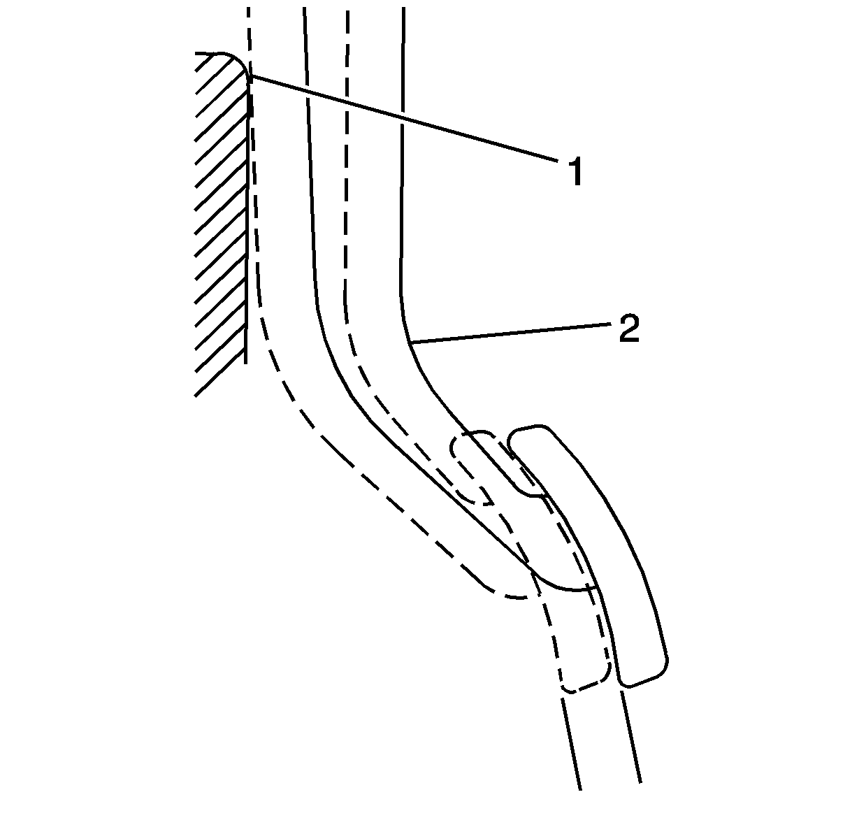
Clutch pedal reserve is necessary in order for the clutch to be completely disengaged and allow proper shifting of the transmission. Clutch pedal reserve is the movement of the pedal after the compressing of the pressure plate assembly springs. Clutch pedal reserve can be felt in the clutch pedal movement as a stiffer or harder pedal towards the bottom of the pedal stroke. Inspect for clutch pedal reserve by depressing the clutch pedal (2) and feeling for a stiffer stroke 25 mm (1 in) from the floor (1).
In order to test to determine if the clutch is properly releasing, and the hydraulic system is functioning properly:
- Depress the clutch pedal fully to disengage the clutch.
- Shift into a low gear, either 1st or reverse.
- Slowly shift out of the gear, only to disengage the synchronizer sleeve from the speed gear engagement teeth.
- Let up on the pedal, to engage the clutch.
- Depress the clutch pedal and shift back into gear.
If the clutch is releasing properly, you should be able to engage the gear without grinding after 4-5 seconds, which is the time for the clutch disc to quit spinning.
