Disassemble Procedure
Important: If a bearing is found to be defective, it is not recommended that the bearing be replaced separately. The bearing may only be available in a sub assembly.
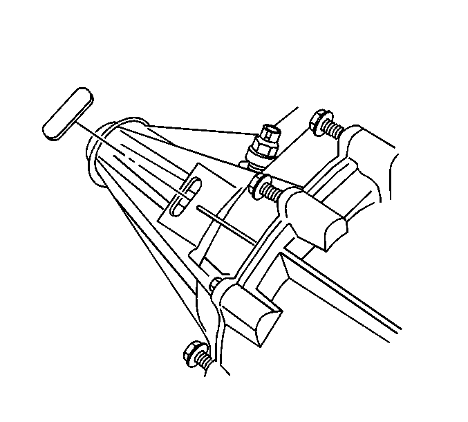
- Remove the rubber plug from the transfer case.
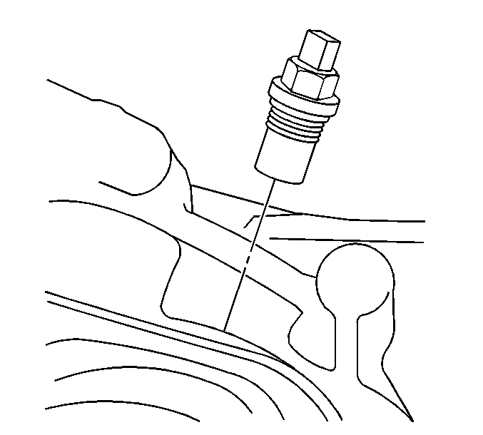
- Remove the transfer case speed sensor.
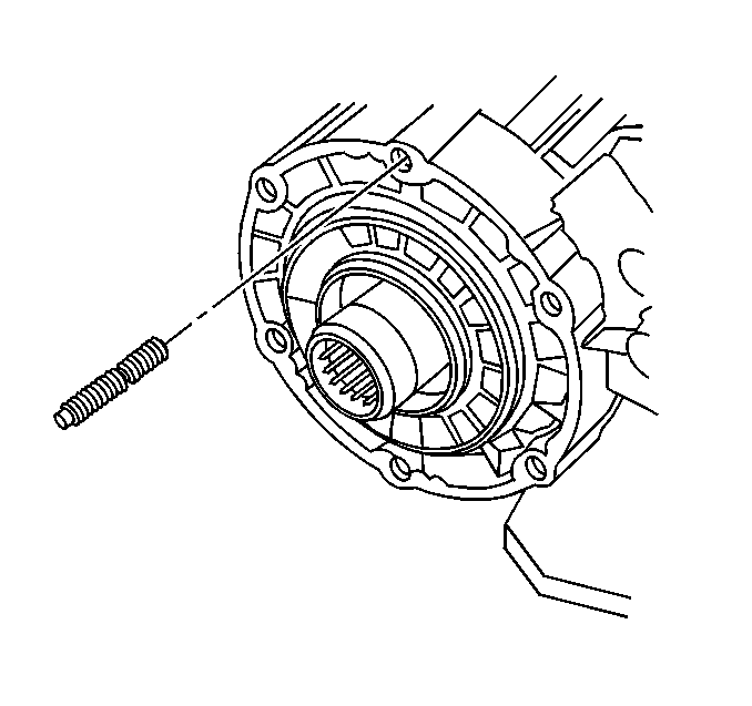
- Remove the mounting studs (only if damaged).
- Remove the input shaft seal.
- Remove the rear output shaft seal.
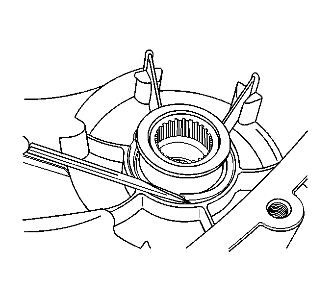
- Insert a flat-tipped screw driver in the inner race.
- Pry the inner race back.
- Insert a small pry bar in the inner race.
- Remove the inner race from the seal.
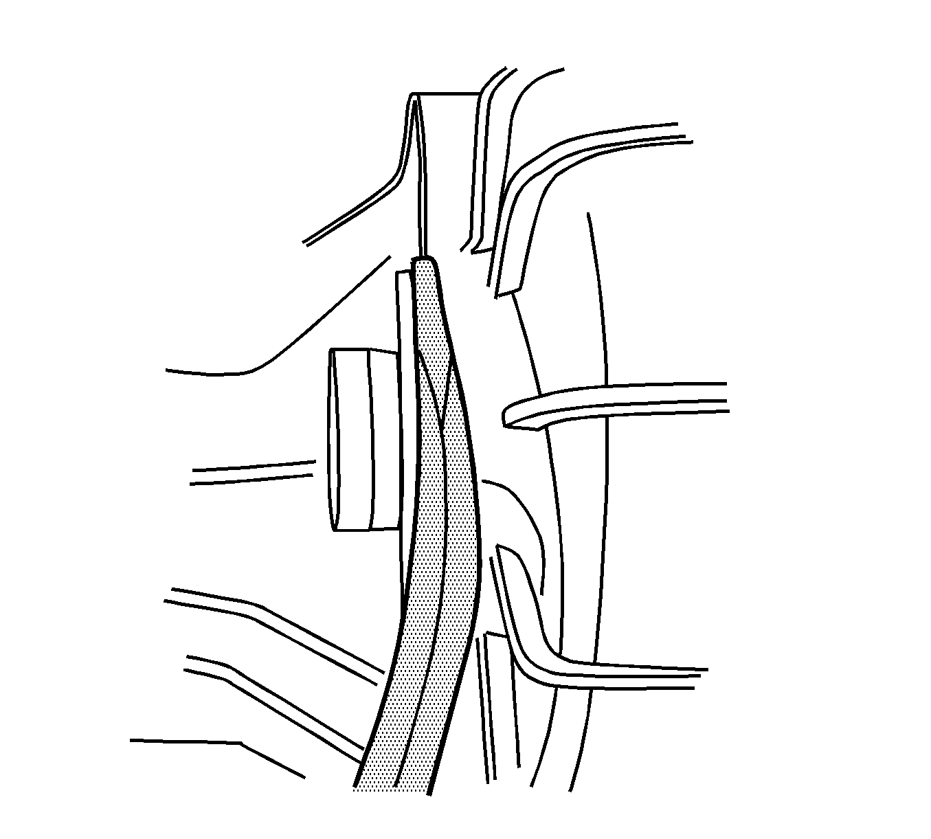
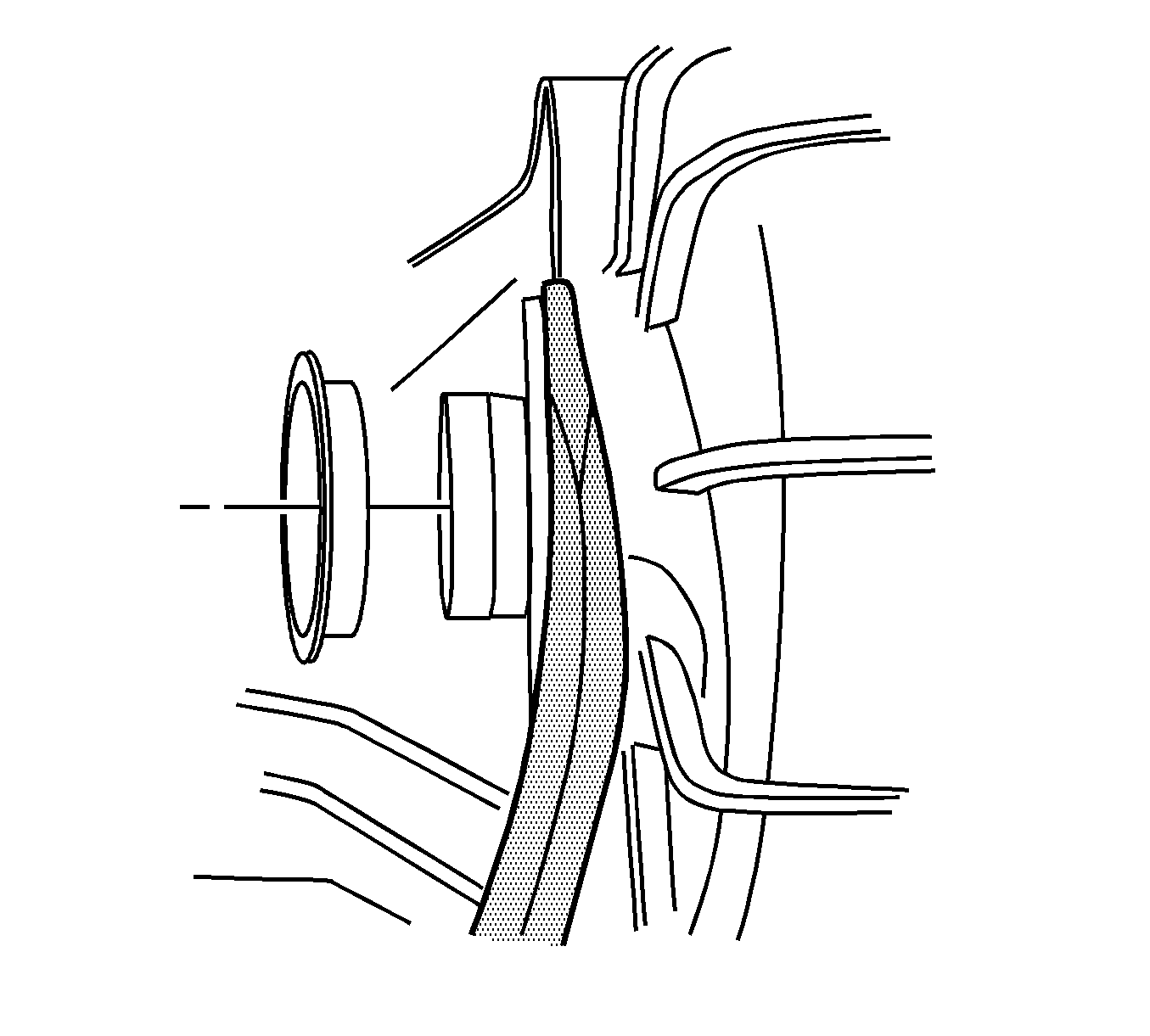
- Insert a flat-tipped screw driver or a small pry bar between the lip of the outer lip of the front output shaft seal and the transfer case.
- Remove the remaining part of the front output shaft from the transfer case.
- Remove the transfer case bolts.
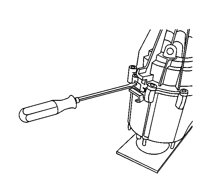
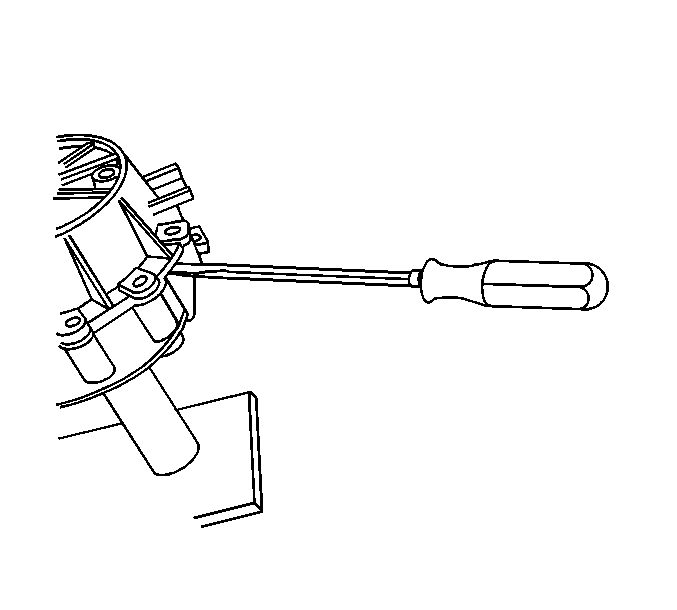
- Insert a flat bladed screw driver in the slot on the left side of the transfer case.
- Insert a flat bladed screw driver in the slot on the right side if the transfer case.
- With equal pressure, press down on the screw drivers.
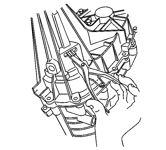
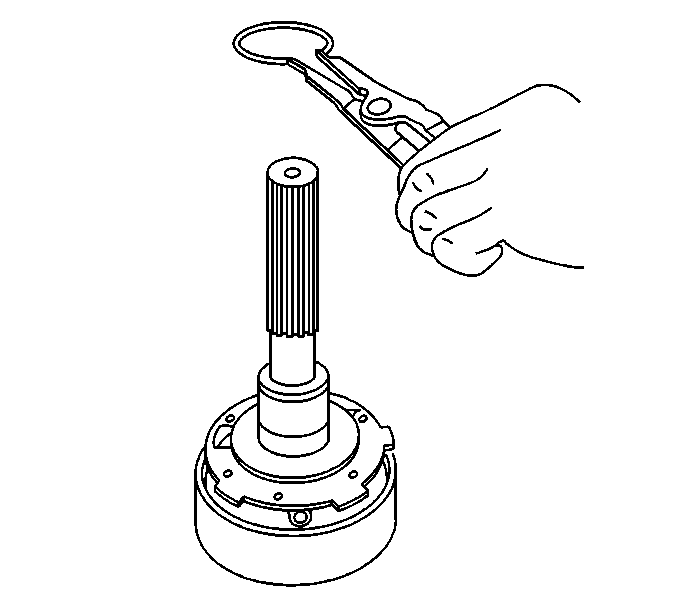
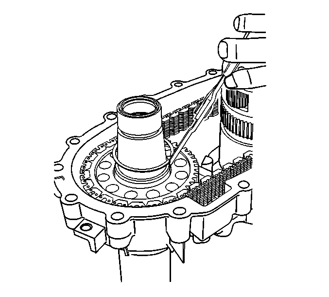
- Insert a pair of snap ring pliers into the slot.
- Using the snap ring pliers, open the outer rear output shaft bearing retaining ring.
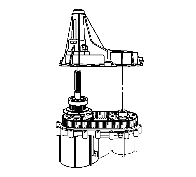
- Remove the rear case half from the front case half.
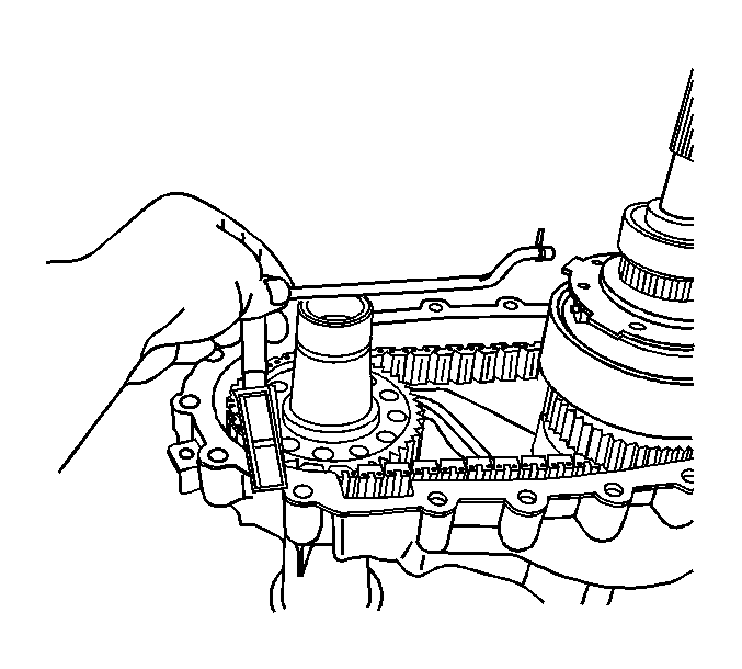
- Remove the oil pump screen assembly.
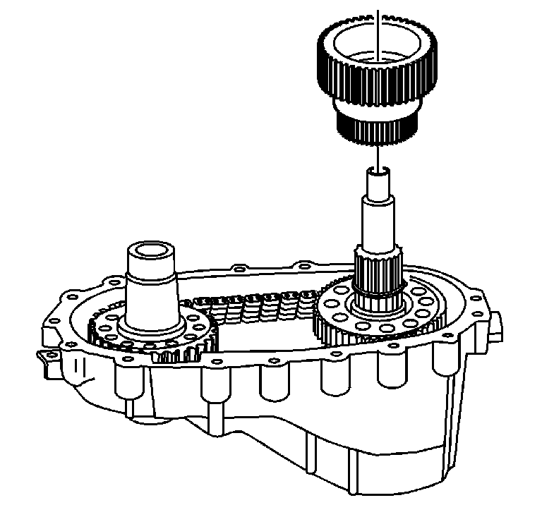
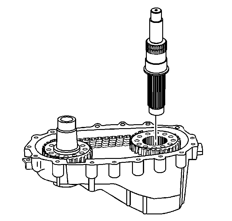
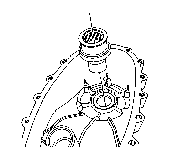
- Remove the rear output shaft assembly.
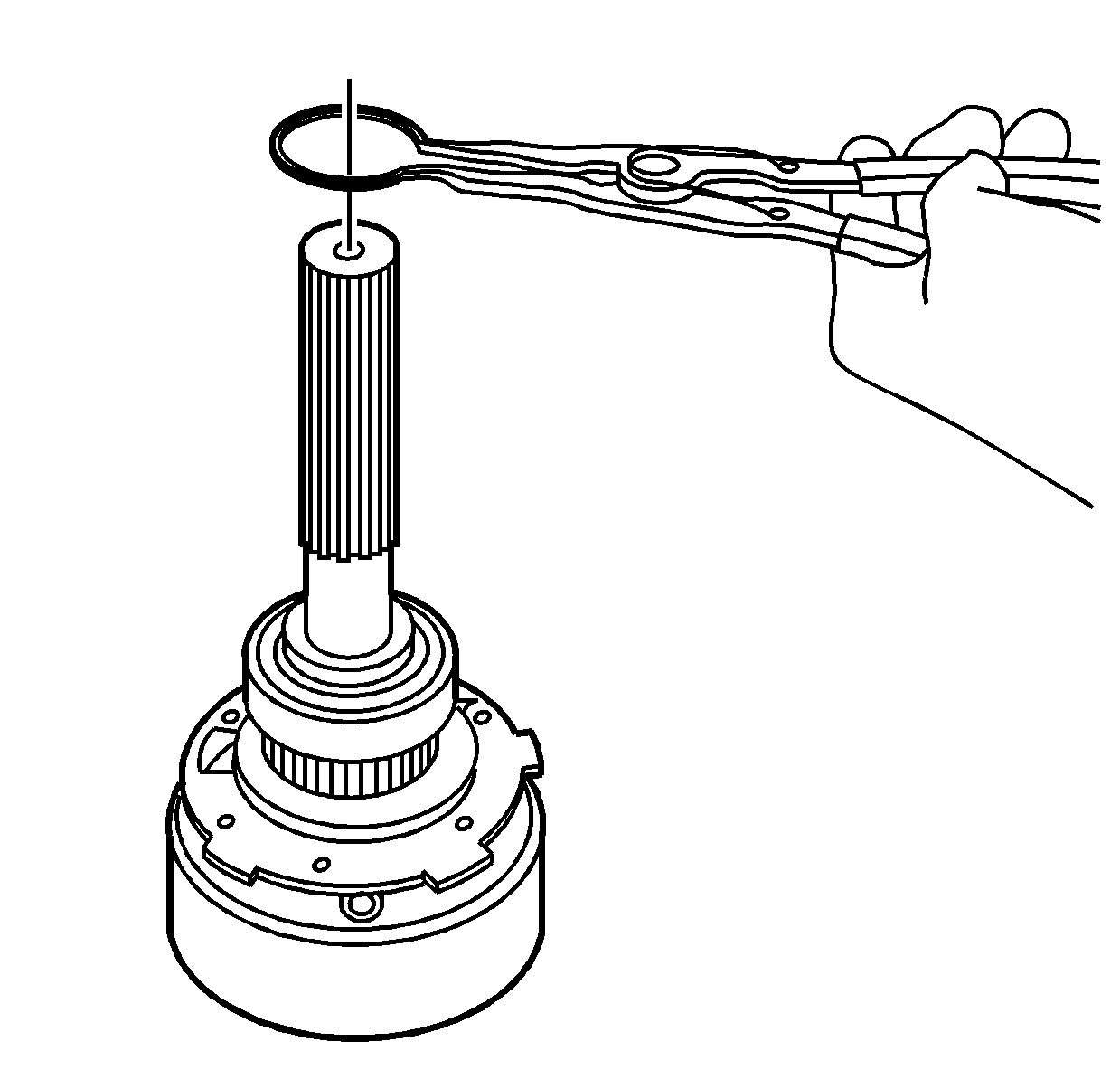
- Remove the rear output shaft bearing retaining ring.
- Using the J 22912-B and a press, remove the input gear bearing.
- Using the J 22912-B and a press, remove the tone wheel.
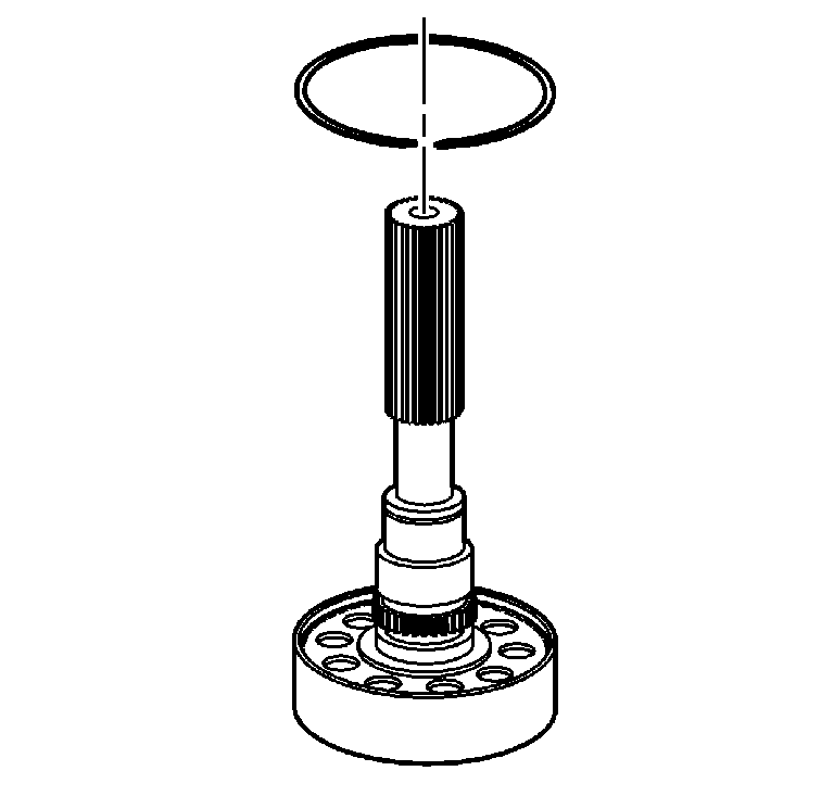
- Remove the oil pump retaining ring.
- Remove the oil pump assembly.
- Using a flat bladed screwdriver, unseat the annulus retaining ring.
- Remove the annulus gear retaining ring.
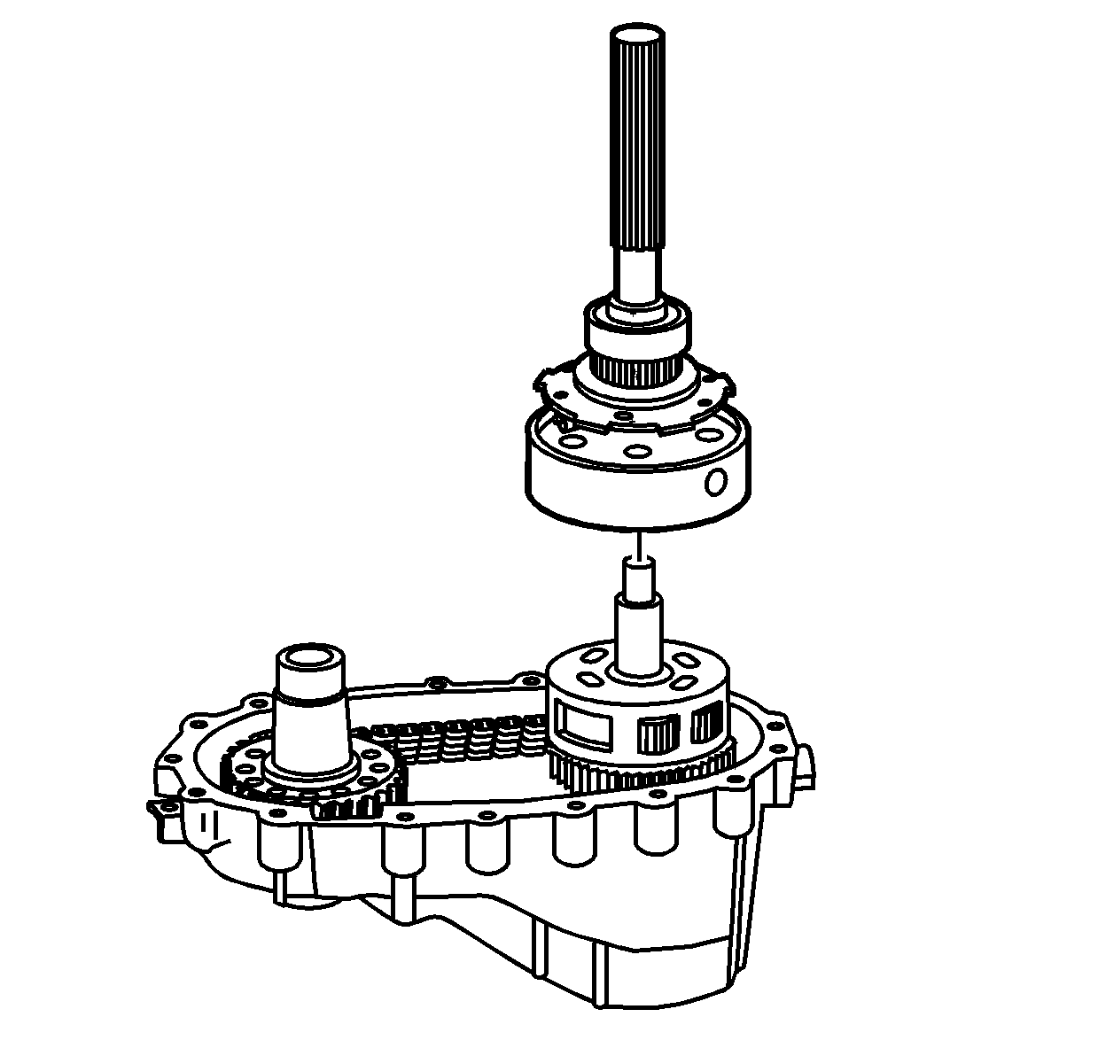
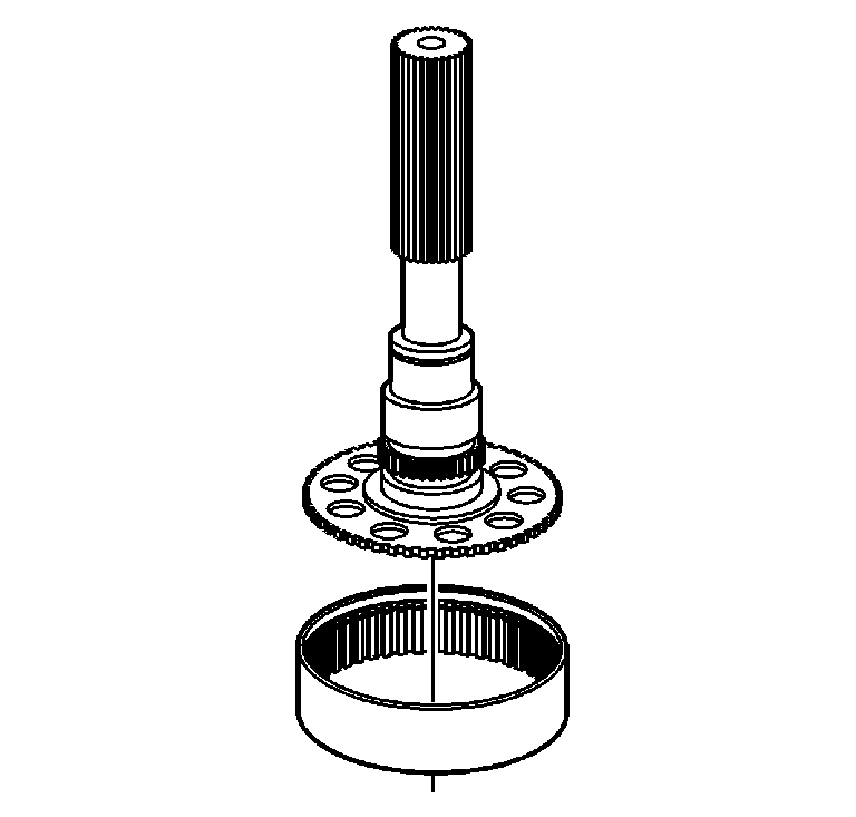
- Remove the rear output shaft.
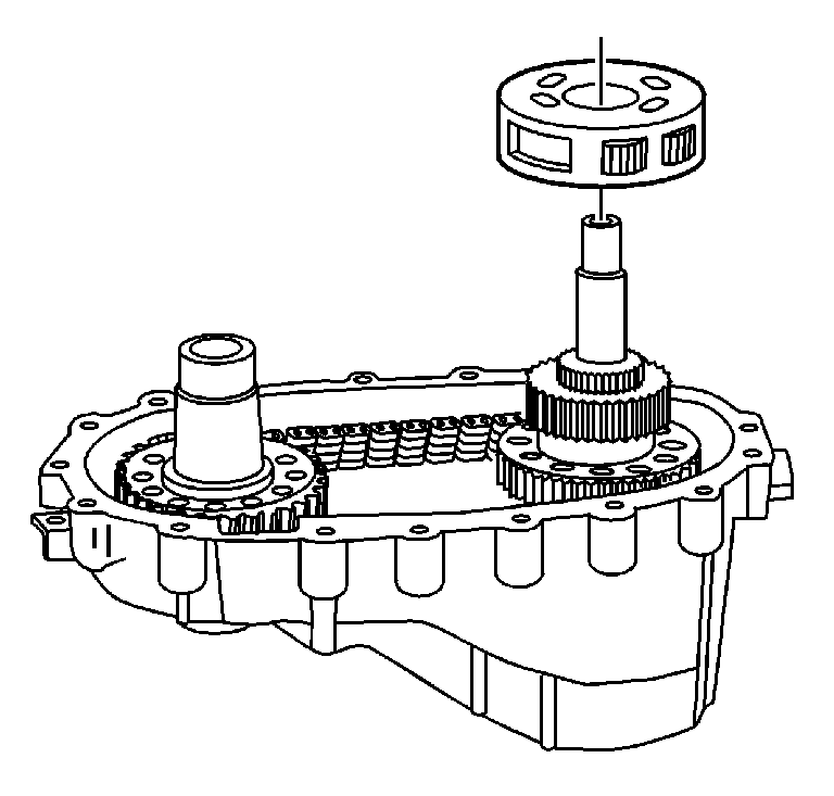
- Remove the carrier assembly.
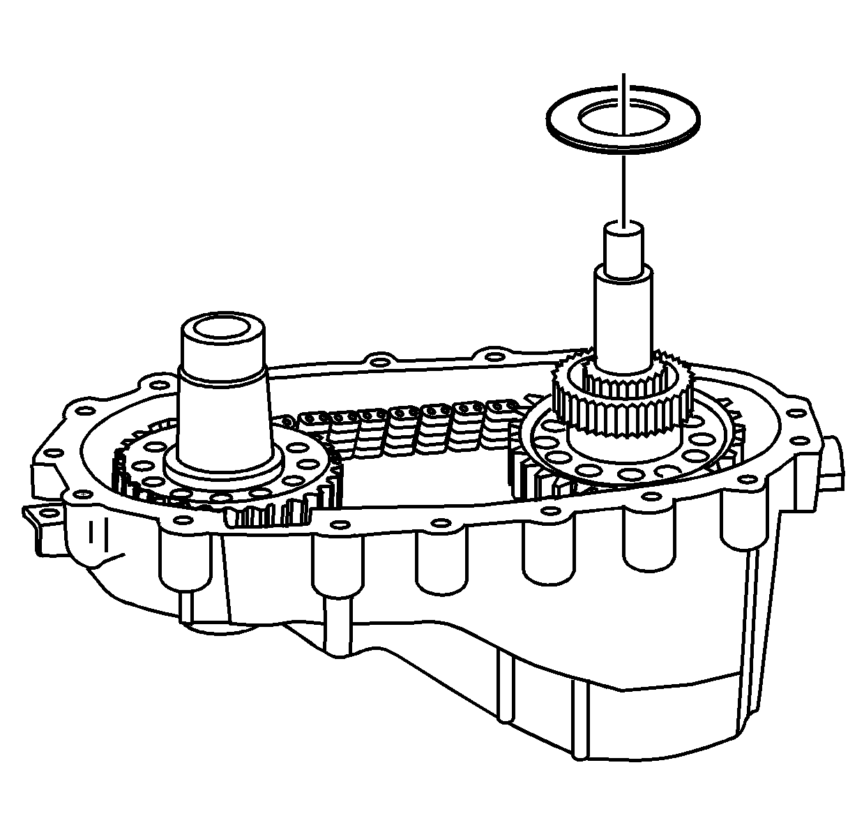
- Remove the carrier assembly thrust washer.
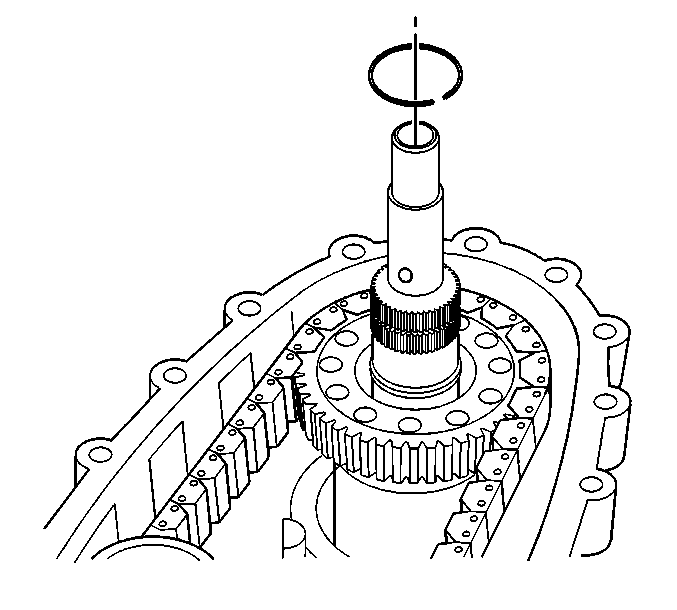
- Remove the carrier retaining ring.
- Remove the sun gear.
- Remove the mainshaft.
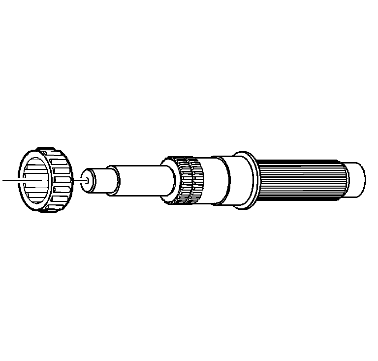
- Remove the needle roller bearing.
- Remove the driven sprocket retaining ring.
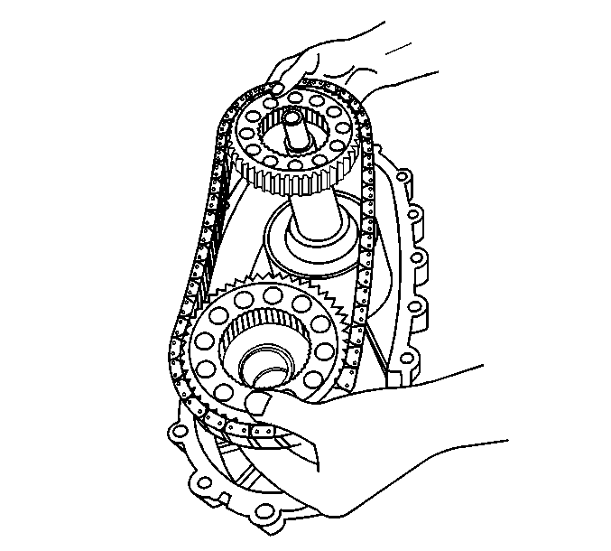
- Remove the drive chain assembly.
- Remove the viscous coupling
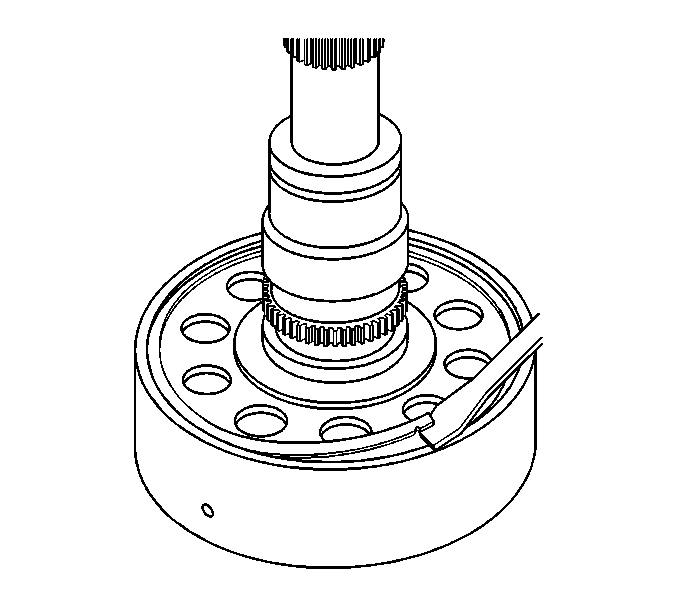
- Using a flat bladed screwdriver, remove the input gear bearing retaining ring from the groove.
- Remove the input gear bearing retaining ring.
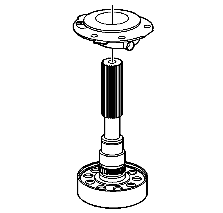
- Remove the input gear assembly.
- Remove the input gear bearing retaining ring.
- Using a press, remove the input gear bearing.
- Using a press, remove the front output shaft assembly.
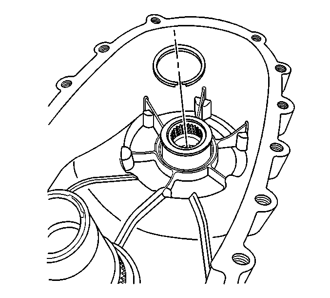
- Remove the front output shaft bearing retaining ring.
- Using the J 22912-B and a press, remove the front output shaft bearing.
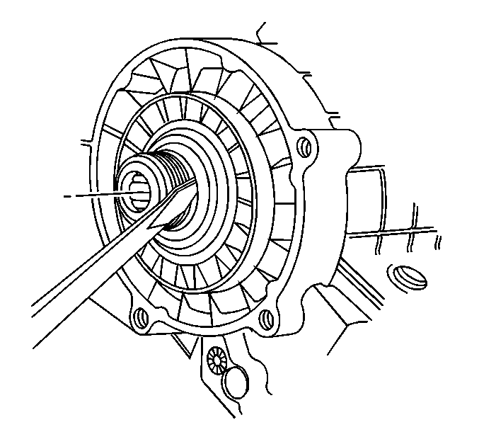
Notice: Do not damage the sealing surfaces of the transfer cases or the shafts when prying the seals for removal. Damaging the sealing surface may cause leakage or require replacement of the damaged component.
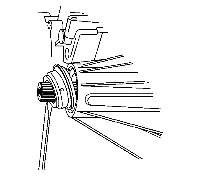
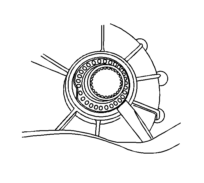
Notice: Do not damage the sealing surfaces of the transfer cases or the shafts when prying the seals for removal. Damaging the sealing surface may cause leakage or require replacement of the damaged component.
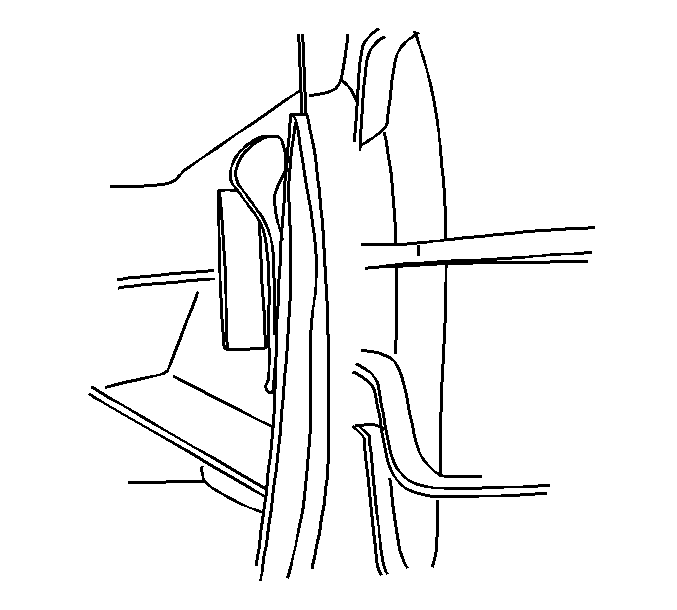
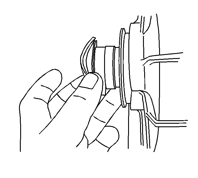
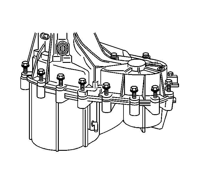
Important: Mark the location of the retaining bolts when removed so that they can be reinstalled in there proper location.
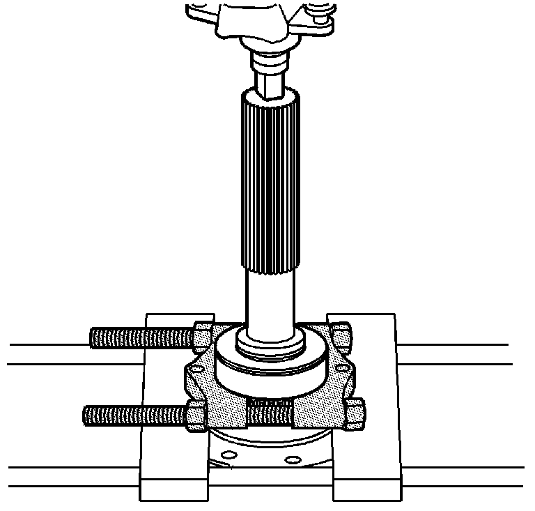
Important: When performing the following service procedure, reverse the way the J-22912-01 is normally installed. This will allow greater tool contact area when removing the input shaft bearing
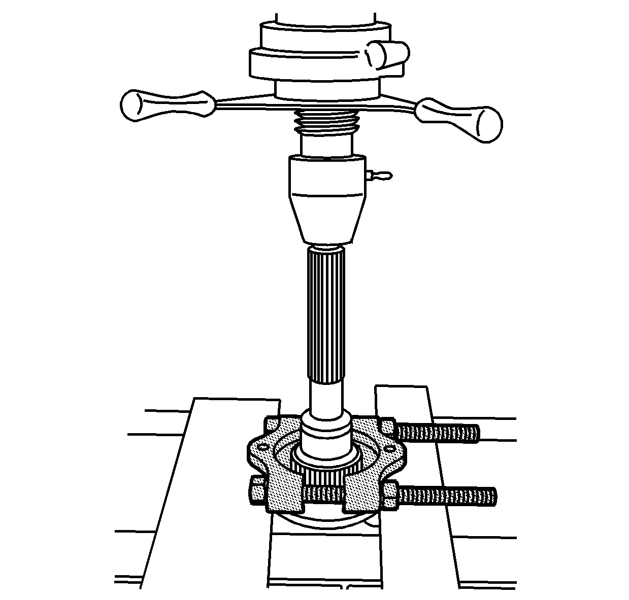
Important: Use a screw pocket screwdriver to move the oil pump retaining ring down away from the tone wheel. This will ensure that the J-22912-01 will not get caught on the retaining ring.
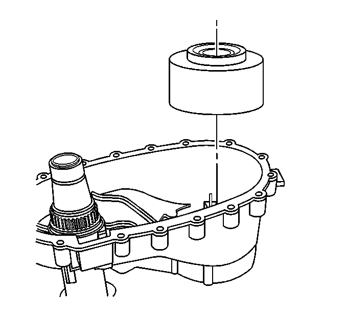
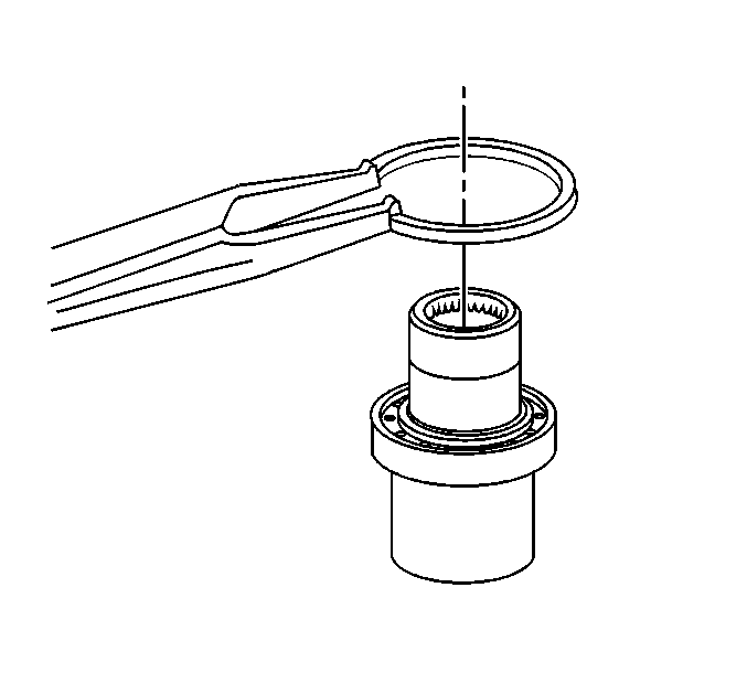


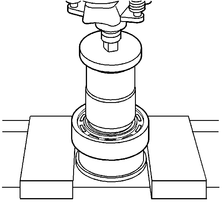
Important: When performing the following service procedure, reverse the way the J-22912-01 is normally installed. This will allow greater tool contact area when removing the front output shaft bearing
