HARD BRAKE PEDAL FEEL POWER BRAKE KIT AVAILABLE

MODELS: 1986-87 S/T MODELS WITH 2.8L V6 ENGINES
A condition described as an intermittent hard brake pedal feel may be caused by reduced vacuum at the brake booster. A power brake kit has been developed to resolve this concern.
Before kit installation, the engine idle speed and Throttle Position Sensor (TPS) must be inspected and/or adjusted according to the following procedure:
MINIMUM IDLE SPEED CHECK AND ADJUSTMENT
IMPORTANT: --------- The throttle stop screw used for regulating minimum idle speed is adjusted at the factory. The screw is covered with a plug to discourage unauthorized adjustments.
Engine RPM must be checked with the engine at normal operating temperature.
1. Remove air cleaner, adapter, and gaskets. Discard gaskets.
2. Plug any vacuum line ports as required.
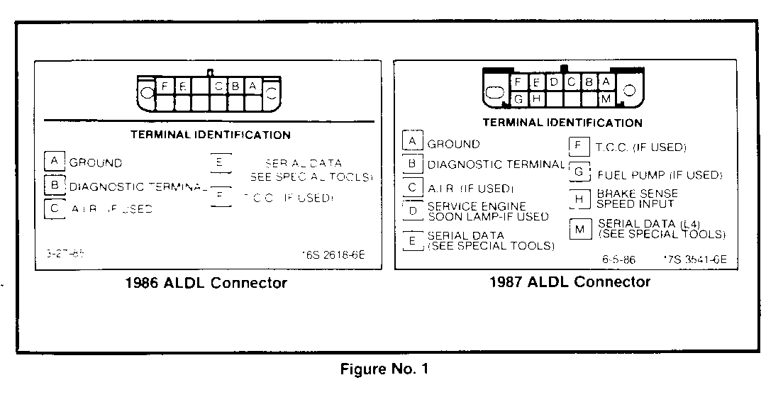
3. With the idle air control (IAC) valve connected, ground the diagnostic terminal of the ALDL connector (See Figure No. 1).
4. Turn on ignition, DO NOT START ENGINE. Wait at least 30 seconds (this allows IAC valve pintle to extend and seat in throttle body).
5. With ignition ON, disconnect IAC valve electrical connector then turn ignition OFF.
6. Remove ground from Diagnostic Terminal. Connect a tachometer to C terminal (TACH) of the primary coil or connect a scan tool to the ALDL and start the engine.
7. Idle speed must be 700 rpm +/- 25 rpm.
If the idle speed is correct:
1. Turn ignition OFF and reconnect the IAC valve electrical connector.
2. Unplug any plugged vacuum line ports.
If the idle speed is not correct:
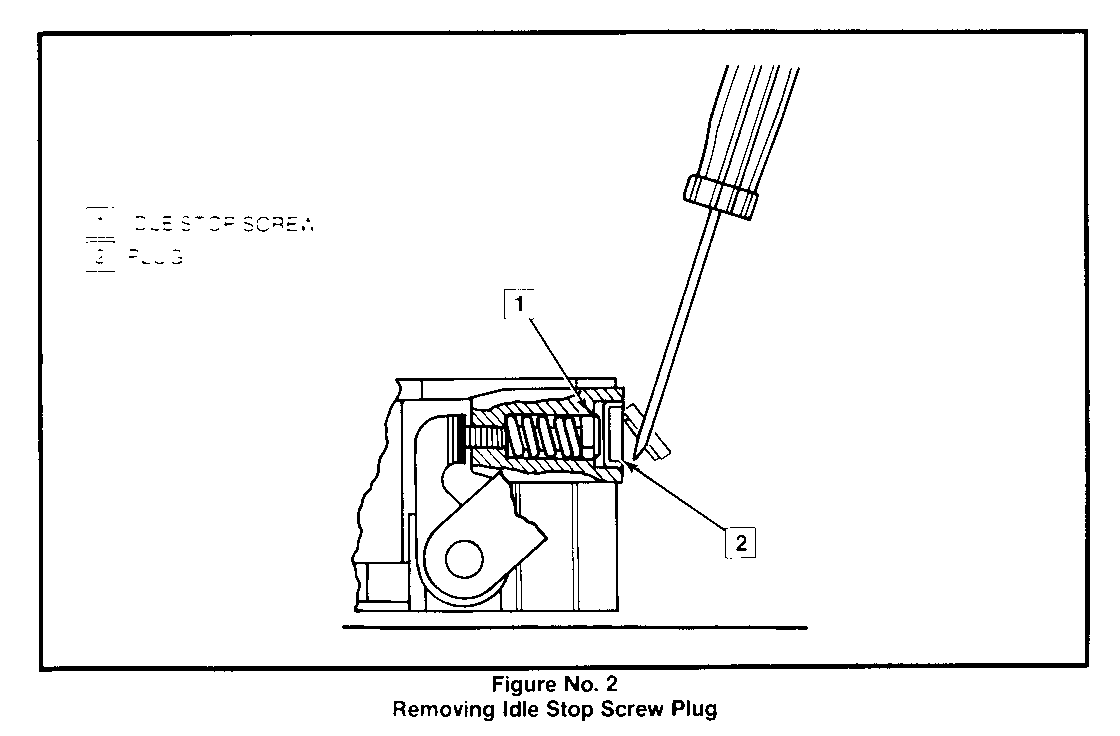
1. Pierce the plug with an awl, then applying leverage, remove the plug to expose the idle speed stop screw (Figure No. 2).
2. Adjust the idle speed stop screw to obtain 700 rpm +/-25 rpm in neutral for the 2.8L engine.
THROTTLE POSITION SENSOR (TPS) CHECK AND ADJUSTMENT
(Throttle Lever Side of TBI Unit)
(1986 Model)
1. Locate the TPS production number on the terminal connector of the TPS housing. All Throttle Position Sensors (TPS) numbered 75906 should be updated to the current design, P/N 17111725. If the TPS is not numbered 75906, proceed to Step 2.
Replacement Procedure
A. Unplug the harness from the switch.
B. Remove the two (2) attaching screws and retainers.
C. Install the new TPS on throttle body assembly, while lining up the TPS lever with the TPS drive lever on throttle body.
(1986-87 Models)
2. Check TPS Voltage.
A. Connect digital voltmeter, J-29125-A, or equivalent, using connector in tool J - 35616 to the TPS terminal A and terminal B. An ALDL scanner can also be used to read TPS output voltage.
B. With ignition "ON", engine stopped, the TPS voltage should be between .42 and .45 volts (1986) and .42 and .54 volts (1987).
C. If the voltage is out of range, loosen the screws and rotate the TPS until voltage is within specifications.
D. If the above voltage limitation cannot be obtained, replace the TPS with P/N 17111725.
E. Remove the voltmeter and jumpers if used, and reconnect the TPS connector to the sensor.
F. Tighten TPS screws to 4.0 Nm (35 lb in).
3. Unplug any plugged vacuum line ports.
POWER BRAKE KIT INSTALLATION
After verifying engine idle speed and TPS operation, the following procedure should be used to install the power brake kit, P/N 15602668.
1. Disconnect cable at the negative battery terminal.
2. Apply parking brake.
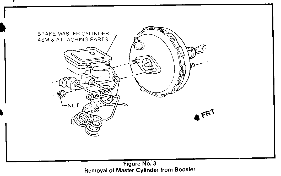
3. Remove the master cylinder and proportioning valve assembly from the brake booster. Do not disconnect any brake lines. See Figure No. 3.
4. Disconnect the vacuum tube, hose and filter assembly from the booster check valve and at the intake manifold. Discard this entire assembly along with the manifold fitting.
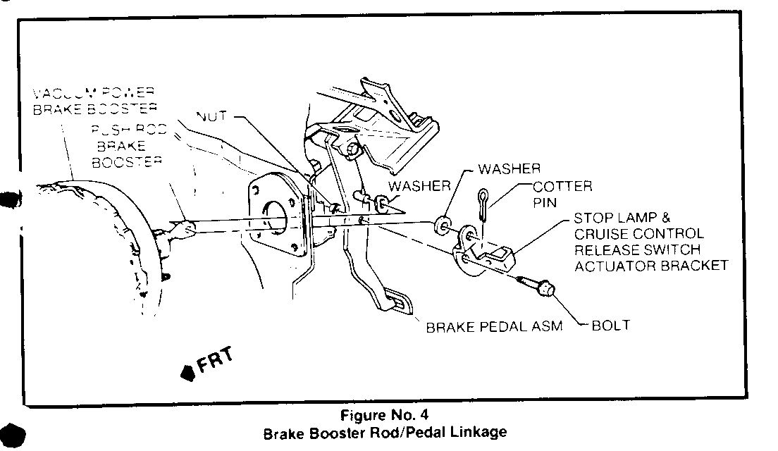
5. Disconnect the brake booster pushrod, refer to "Brake Pedal Replacement" Section 5 in the service manual. See Figure No. 4.
6. Remove vacuum brake booster mounting nuts (inside vehicle).
7. Remove vacuum brake booster from vehicle and discard.
8. Remove old seal from cowl panel.
9. With pipe thread sealant, Loctite P/N 1052080 or equivalent, on threads,install the brake pipe vacuum fitting in the intake manifold.
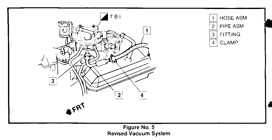
10. Apply pipe thread sealant to the nut on the pipe assembly (P/N 10069245) and assemble the pipe assembly to the manifold fitting Install vacuum hose (P/N 15602667) to the manifold pipe and secure with the clamp. See Figure No. 5.
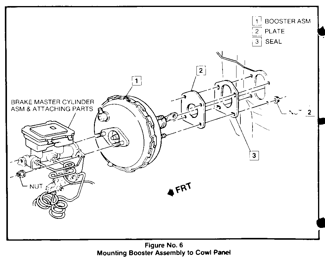
11. Install adapter plate and new seal on booster mounting studs. Install brake booster assembly on the vehicle. Torque booster nuts to 20 Nm (15 lb ft). See Figure No. 6.
12. Reinstall booster pushrod.
13. Reinstall brake master cylinder and proportioning valve to the booster. Torque nut to 27 Nm (20 lb ft).
14. Connect the hose assembly to the booster check valve.
15. Install the air cleaner adapter and new gaskets.
16. Connect the battery cable.
NOTE: ALWAYS ENSURE THAT THE BRAKE SYSTEM IS OPERATIONAL AFTER PERFORMING BRAKE WORK BEFORE RETURNING THE VEHICLE TO THE CUSTOMER.
PARTS LIST
Power Brake Kit (1) 15602668 Kit consists of: Fitting 14102142 Pipe Assembly 10069245 Hose Assembly 15602667 Booster Assembly 18014642 Check Valve Kit 18012017 Adapter Plate 15602644 Seal 14030819 Instruction Sheet 15602669
Use T Op 7375 when performing these procedures. Labor times are as follows:
Check minimum idle speed, 1.0 hr. Cheek TPS sensor numbers, Check TPS voltage and install power brake kit.
Add
If necessary to adjust minimum .1 hr. idle If necessary to install updated .1 hr. TPS sensor
General Motors bulletins are intended for use by professional technicians, not a "do-it-yourselfer". They are written to inform those technicians of conditions that may occur on some vehicles, or to provide information that could assist in the proper service of a vehicle. Properly trained technicians have the equipment, tools, safety instructions and know-how to do a job properly and safely. If a condition is described, do not assume that the bulletin applies to your vehicle, or that your vehicle will have that condition. See a General Motors dealer servicing your brand of General Motors vehicle for information on whether your vehicle may benefit from the information.
