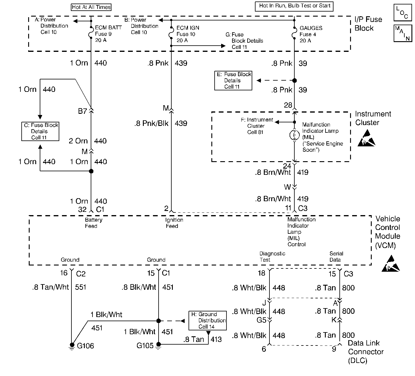
No Serial Data VCM

Circuit Description
There should always be a steady Malfunction Indicator Lamp (MIL) when the ignition is ON and engine stopped. Battery voltage is supplied to the light bulb. The VCM will turn the light on by grounding the MIL control circuit at the VCM.
Diagnostic Aids
Check the DLC and a Tech 1 connector for poor connection. Refer to the Intermittent Conditions symptom table.
Test Description
-
This test confirms that the VCM can communicates with the scan tool.
-
There should be 4-5 volts present.
-
If voltage remains at the DLC when the VCM connector is disconnected, then the serial data circuit is shorted to voltage.
-
This step will check for an open in the serial data circuit.
-
At this point the wiring is OK. The problem is a faulty VCM connection or VCM.
Step | Action | Value(s) | Yes | No |
|---|---|---|---|---|
1 | Was the On-Board Diagnostic (OBD) System Check performed? | -- | ||
Is serial data indicated on the scan tool? | -- | Go to Diagnostic Aids | ||
Connect the J 39200 to the DLC serial data circuit and ground? Is voltage still present | -- | |||
Disconnect the gray VCM connector. Is voltage present? | -- | |||
5 | Repair the serial data circuit for a short to voltage. Refer to Wiring Repairs in Wiring Systems. Is the repair complete? | -- | -- | |
6 | Check the scan tool connection at the DLC. Refer to Wiring Repairs in Wiring Systems. Is the repair complete? | -- | -- | |
Is there continuity on the serial data circuit? | -- | |||
Check the VCM connection. Refer to Wiring Repairs in Wiring Systems. Is the repair complete? | -- | |||
9 | Replace the faulty VCM. Refer to Vehicle Control Module . Is the repair complete? | -- | -- | |
10 | Perform the VCM Programming Procedures. Refer to Vehicle Control Module . Has the programming procedures been completed? | -- | -- | |
11 | Check for an open on the serial data circuit. Refer to Wiring Repairs in Wiring Systems. Is the repair complete? | -- | ||
12 | Check the serial data circuit for a short to ground. Refer to Wiring Repairs Is the repair complete? | -- | -- | |
13 | Confirm Closed Loop operation and no MIL (Service Engine Soon). Is the vehicle in Closed Loop, and no MIL? | -- | System OK | Go to applicable DTC table |
