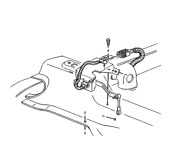
Removal Procedure
Notice: When you are servicing the automatic level control sensor link, ensure that the sensor link and the sensor arm are not damaged. Ensure the sensor arm and the sensor link are properly oriented. Improper orientation of the sensor arm and the sensor link may cause damage to the automatic level control system or the vehicle.
- Raise and support the vehicle. Refer to Lifting and Jacking the Vehicle in General Information.
- Disconnect the automatic level control sensor electrical connector.
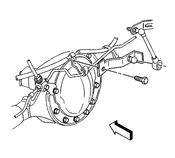
- Remove the automatic level control sensor link from the rear differential bracket ball stud.
- Remove the automatic level control sensor bracket assembly to the rear shock and spare tire crossmember retaining bolts.
- Remove the automatic level control sensor bracket assembly from the vehicle.
- Remove automatic level control sensor link from the automatic level control sensor arm ball stud.
- Remove automatic level control sensor to the bracket bolts.
- Remove automatic level control sensor from the bracket.
Installation Procedure
Notice: When you are servicing the automatic level control sensor link, ensure that the sensor link and the sensor arm are not damaged. Ensure the sensor arm and the sensor link are properly oriented. Improper orientation of the sensor arm and the sensor link may cause damage to the automatic level control system or the vehicle.
- Install the automatic level control sensor to the automatic level control sensor bracket.
- Install the automatic level control sensor to the automatic level control sensor bracket bolts.
- Install the automatic level control sensor link to the automatic level control sensor arm ball stud.
- Install the automatic level control sensor bracket assembly to the vehicle.
- Install the automatic level control sensor bracket assembly to the rear shock and spare tire crossmembers bolts.
- Install the automatic level control sensor link to the rear differential bracket ball stud.
- Connect the automatic level control sensor electrical connector.
- Lower the vehicle.
Notice: Use the correct fastener in the correct location. Replacement fasteners must be the correct part number for that application. Fasteners requiring replacement or fasteners requiring the use of thread locking compound or sealant are identified in the service procedure. Do not use paints, lubricants, or corrosion inhibitors on fasteners or fastener joint surfaces unless specified. These coatings affect fastener torque and joint clamping force and may damage the fastener. Use the correct tightening sequence and specifications when installing fasteners in order to avoid damage to parts and systems.
Tighten
Tighten the automatic level control sensor to the automatic level control
sensor bracket bolts to 4 N·m (35 lb in).
Tighten
Tighten the automatic level control sensor bracket to the rear shock
and spare tire crossmember bolts to 12 N·m (110 lb in).
