Transfer Case Electrical Components
Below, is a list of major components that make up the automatic transfer case system:
Transfer Case Shift Control Switch

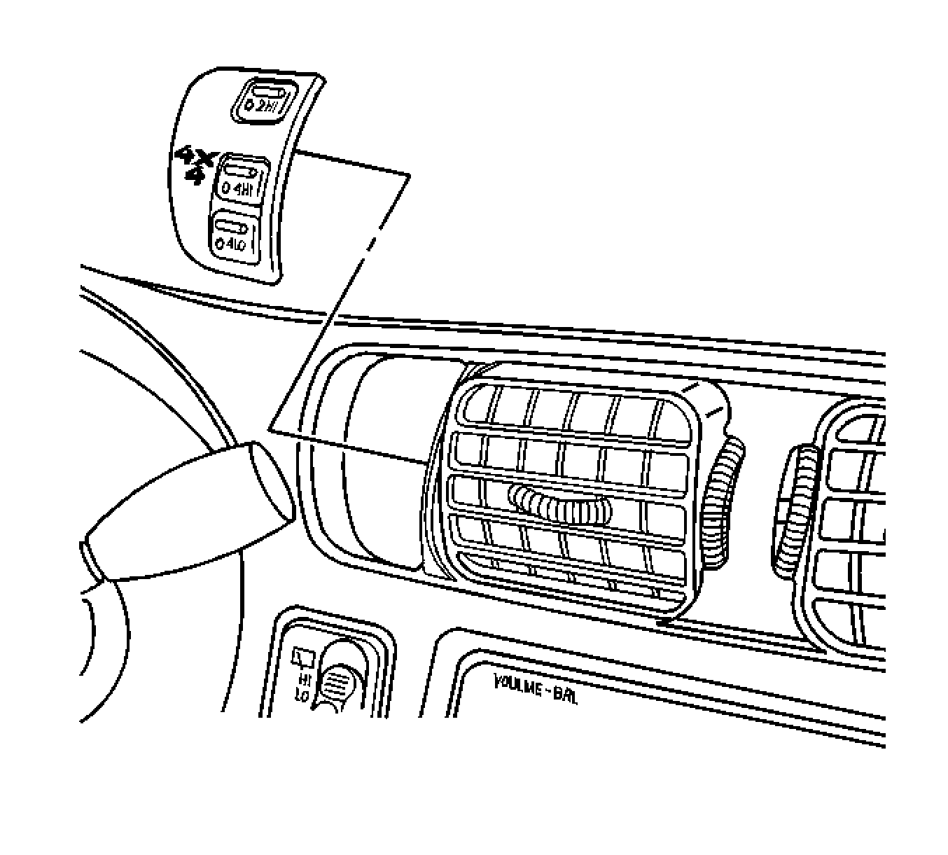
The NVG 233 transfer case features a 3 button shift control switch, located on the instrument panel. When the ignition is in the RUN position, the transfer case shift control module starts monitoring the transfer case shift control switch, to determine if a new mode/gear position has been selected. At a single press of the transfer case shift control switch, the lamp of the new position begins flashing to inform the driver that the transfer case shift control module has received the request for a new mode/gear position. The lamp continues to flash until all shifting criteria has been met and the new mode/gear position has been reached, or has engaged. Once the new mode/gear position is fully active, the switch indicator lamp for the new position remains ON constantly.
The NVG 233 transfer case provides the driver with 3 manual mode/gear positions:
| • | 2HI - 2 Wheel Drive high range |
| • | 4HI - 4 Wheel Drive high range |
| • | 4LO - 4 Wheel Drive low range |
Any of these mode/gear positions may be selected while driving the vehicle. However, the transfer case will not allow a shift into, or out of, 4LO unless the following criteria has been met:
| • | The engine is running. |
| • | The automatic transmission is in Neutral, or the clutch pedal is applied on manual transmissions. |
| • | The vehicle speed is below 5 km/h (3 mph). |
Front Axle Indicator Switch
The front axle indicator switch is mounted to the front axle assembly. When 4WD is selected and all conditions have been met to complete the shift, the transfer case encoder motor shifts the transfer case. The front axle then engages via a cable, and the front axle switch closes. This sends ignition voltage from the 4WD fuse, through the switch, to the PCM. This input informs the PCM that the front axle has been engaged.
Transfer Case Encoder
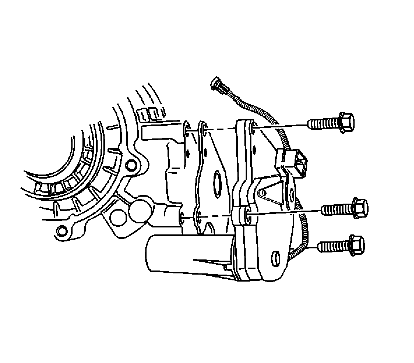
The encoder is mounted to the transfer case encoder motor assembly and is replaced only as an assembly. The encoder converts the sector shaft position into electrical signal inputs to the transfer case shift control module. The module detects the position that the transfer case is in, by monitoring the 4 encoder channels, A, B, C, and P. These inputs translate into 2HI, 4HI, and 4LO, or whether the motor is still in transition between gears.
Transfer Case Encoder Motor

The transfer case encoder motor consists of a permanent magnet (PM) DC motor and gear reduction assembly. It is located on the left hand side of the transfer case. When activated, it turns the sector shaft of the transfer case clockwise or counter clockwise to shift the transfer case. The sector shaft also applies the clutch, which engages the front propshaft. The encoder motor is controlled with a pulse width modulated (PWM) circuit, provided by the transfer case shift control module. This circuit consists of a driver on both the Motor Control A and Motor Control B circuits. The encoder motor is bi-directional, to allow the motor to shift the transfer case from 2HI or 4HI, to 4LO positions.
Transfer Case Shift Control Module

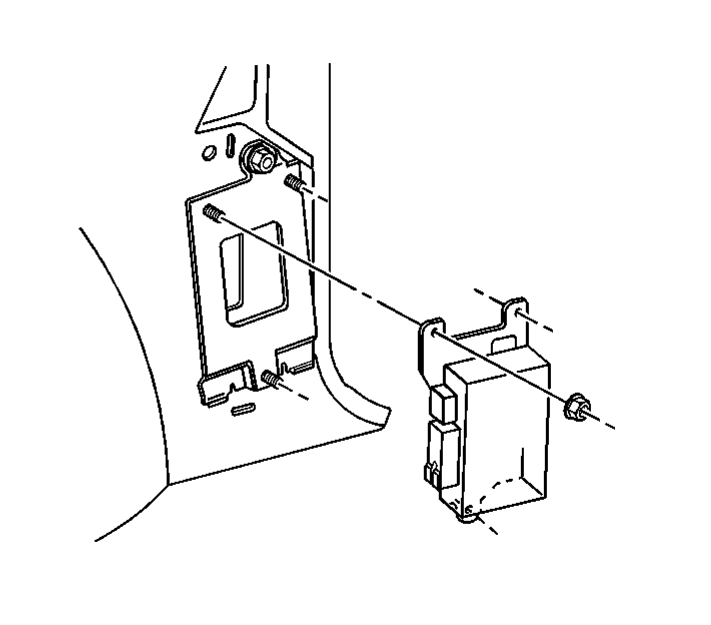
The transfer case shift control module receives input signals, processes the signal information, develops output signals, and sends the output signal, in order to control the shifting of the transfer case.
The transfer case shift control module receives input signals from the transfer case control switch buttons, the park/neutral position (PNP) switch for vehicles with automatic transmissions, the clutch position switch for vehicles with manual transmissions, the powertrain control module (PCM) that supplies the vehicle speed signals, the encoder motor that provides actual mode and range information signals, the data link connector pin D3 that actuates diagnostic enable, power for the module and motor supplies, and the ground used for return lines at the module.
The transfer case shift control module sends signals to the transfer case encoder motor to initiate mode and range shifts, the transfer case control switch indicator lamps to provide transfer case status information, the diagnostic DTCs which are outputted via the shift control switch indicator lamps, and the encoder power.
In order to ensure the electronic shift system is operating properly, the transfer case shift control module continually performs diagnostics tests on itself, and other parts of the electronic shift system, when the ignition switch is in the RUN position.
Below, are the different types of system tests that the transfer case shift control module continually performs.
Data Memory Retention Test: The transfer case shift control module inspects the stored diagnostic trouble code memory, to find out if the memory has changed since the ignition switch was last positioned to OFF. This test determines if the RAM standby power supply has been interrupted. If the transfer case shift control module detects a RAM standby power supply interruption, the shift control module stores a DTC of 1 indicating RAM standby power failure. This condition occurs when the shift control module is disconnected from the wiring harness or battery power is removed.Encoder Signal Test: The transfer case shift control module tests the encoder signal in order to verify that the transfer case is in either 2HI, 4HI, or 4LO.
Encoder Switch Monitor Test: While the transfer case shifts, the encoder within the encoder motor assembly is monitored for the proper operating sequence. If, during a shift, the encoder changes to an incorrect position, an error counter in the transfer case shift control module starts to count the number of times the encoder fails. If the encoder fails 8 times, the shift control module produces a DTC of 2, indicating an encoder fault. If an encoder fault is detected, the shift control module sends a signal, in order to default the rail shift pattern in the encoder, in order to allow for only shifts into 2HI and 4LO. To protect against transient, random encoder faults caused by vibration, contamination, and electrical noise, the error counter reduces the count by 1 each time a good encoder value is detected. The encoder must fail 25 percent of the time for the shift control module to store a DTC of 2 and indicate a damaged encoder.
Motor and Relay Voltage Tests: When the encoder motor is turned ON or OFF, the motor and the electrical circuits are tested, in the de-energized and energized condition. If 1, or both of the voltage relays fail to detect the proper voltage after energizing or de-energizing, the shift is aborted by the shift control module and a DTC of 3 is stored, in order to indicate a faulty shift control module motor circuit. If 1 or both relays fail to detect the proper voltage after de-energizing, both relays are turned ON by the shift control module, in order to prevent the motor from running. The shift control module then stores a DTC of 3, to indicate a faulty shift control module motor circuit. All of the status lamps blink 3 times, stop, and repeat the blinking continuously, in order to alert the driver that the electronic shift system requires immediate repair. The battery drains when this condition occurs, regardless of the ignition switch position.
RAM/ROM Test: The transfer case shift control module compares the current internal operating program with a stored operating program. This comparison allows the shift control module to evaluate if the shift control module RAM and ROM are operating properly. If the shift control module detects a condition with the internal operating program, a diagnostic trouble code (DTC) of 4 is stored indicating the shift control module memory is damaged.
