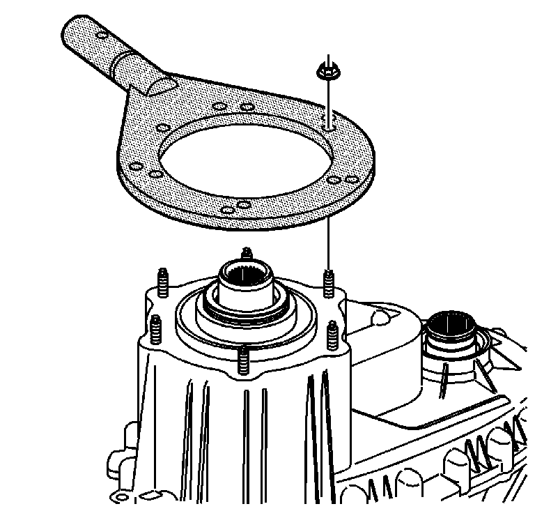
- Attach the J 45759
to the transfer case using the adapter
studs or bolts. The transfer case disassembly procedures can be performed
with the case mounted to the J 45759
.
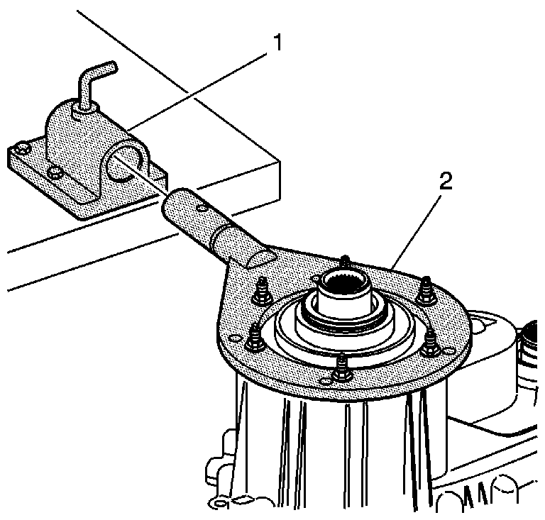
- Mount the J 3289-20
(1) to a sturdy workbench.
- Install the J 45759
(2) into J 3289-20
(1) and secure with a pivot pin.
Important: If a bearing is found to be defective, it is not recommended that the
bearing be replaced separately. The bearing may only be available in a
subassembly.
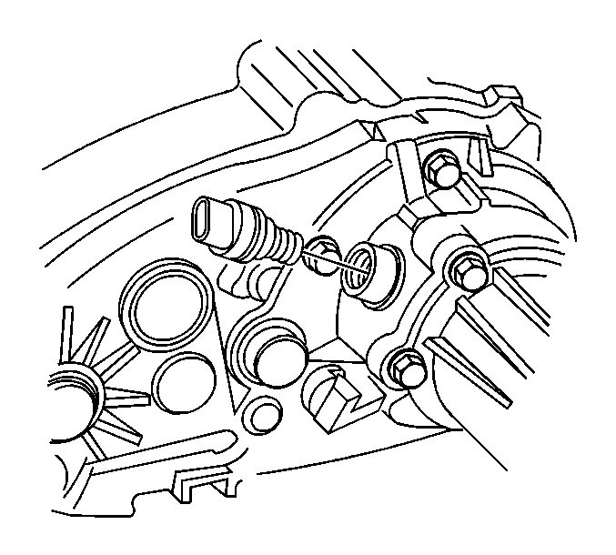
- Remove the speed sensor.
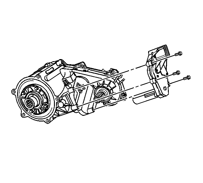
- Remove the encoder motor
mounting bolts.
- Remove the encoder motor assembly.
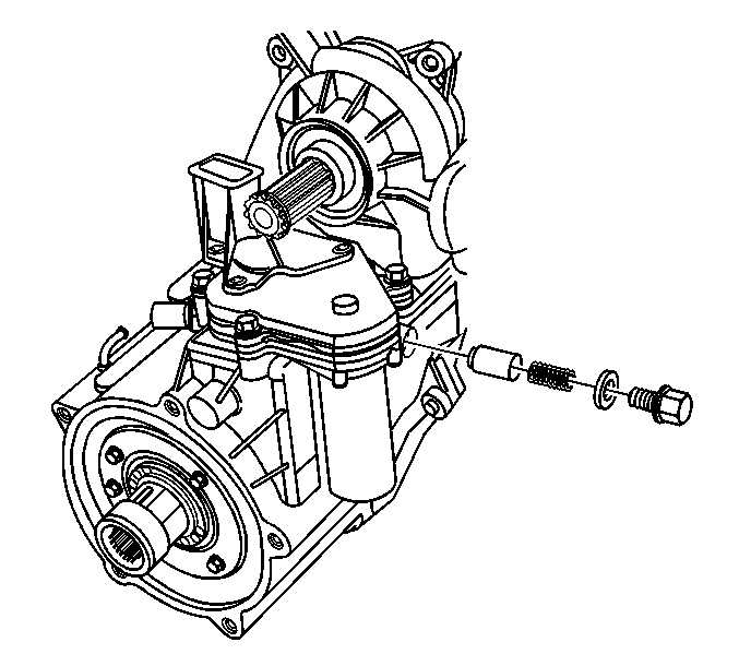
- Remove the detent assembly.
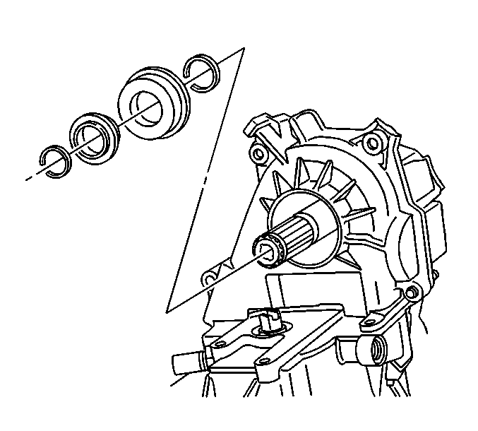
- Remove the first front
output shaft retaining ring.
- Remove the front output shaft rubber washer.
- Remove the front output shaft seal.
- Remove the second front output shaft retaining ring.
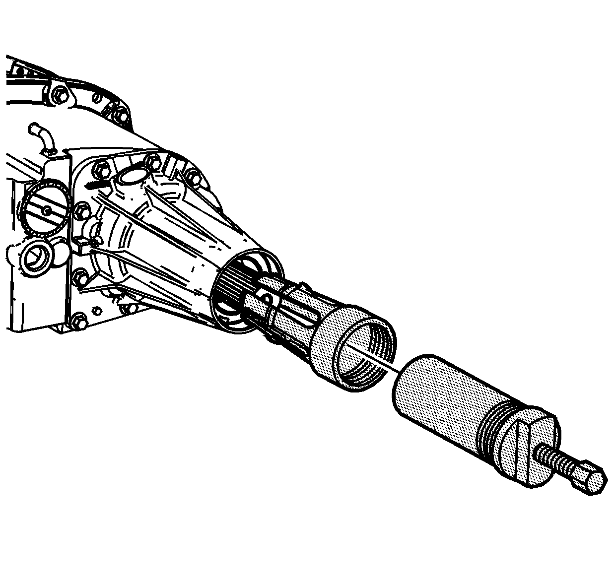
- Inspect the rear output shaft bushing
for scoring or wear.
- Remove the rear output shaft bushing using the J 45380
.
| 13.1. | Install the finger section of the J 45380
in front of the bushing. |
| 13.2. | Install the tube and forcing screw assembly to the finger section.
Ensure the forcing screw is backed out. |
| 13.3. | Using a wrench on the forcing screw, remove the rear output shaft
bushing. |
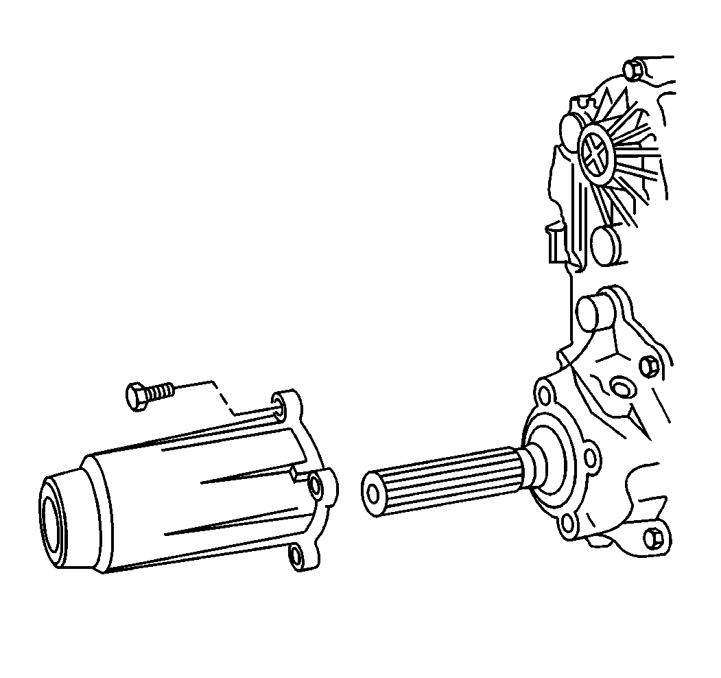
- Remove the rear extension
housing mounting bolts.
- Remove the rear extension housing.
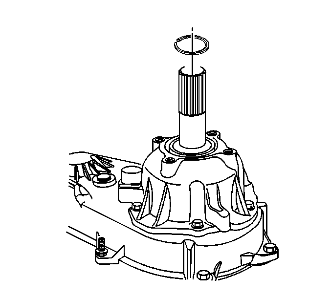
- Remove the rear output
shaft retaining ring.
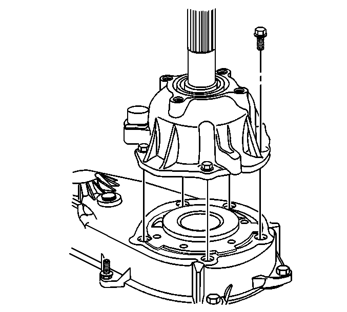
- Remove the rear output
shaft bearing housing mounting bolts.
- Remove the rear output shaft bearing housing.
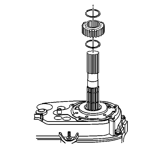
- Remove the first tone
wheel retaining ring.
- Remove the tone wheel.
- Remove the second tone wheel retaining ring.
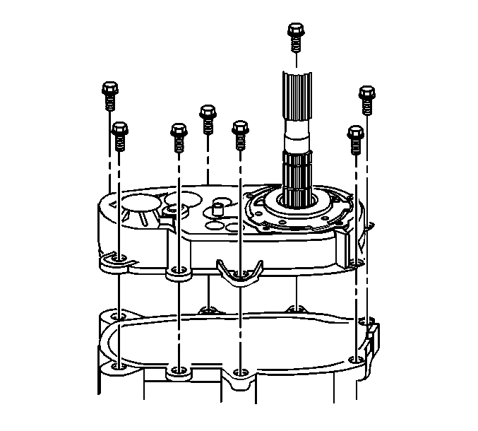
- Remove the transfer case
retaining bolts.
- Remove the rear case half from the front case half.
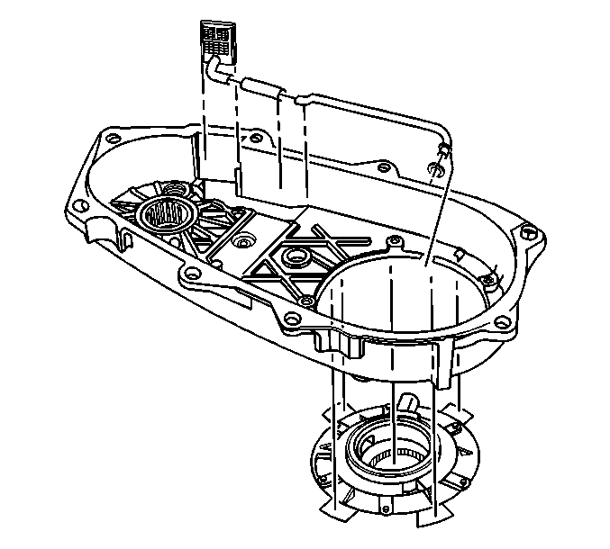
- Remove the oil pump pick-up
assembly.
- Remove the oil pump assembly.
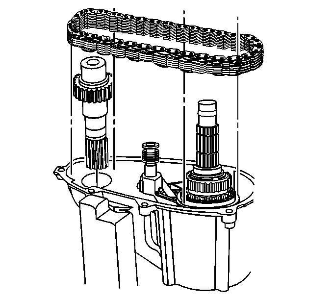
Important:
| • | If the drive chain is to be used again, mark the relationship of the
drive chain to the sprockets. This will ensure that the wear pattern on
the drive chain and the drive sprockets will be matched during assembly. |
| • | The drive sprocket is part of the synchronizer assembly and can only
be removed from the front of the rear output shaft. |
| • | The driven sprocket is part of the front output shaft and not a separate
part. |
- Remove the drive chain and the front output shaft.
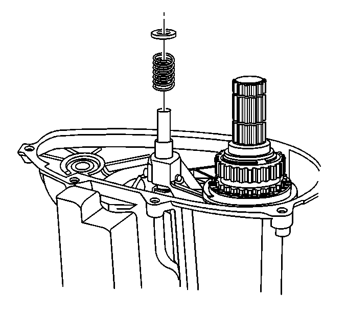
- Remove the mode fork retaining
spring assembly.
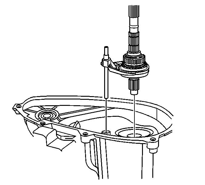
Important: When performing the following service procedure, remove the rear output
shaft and the mode fork as an assembly.
- Remove the rear output shaft assembly.
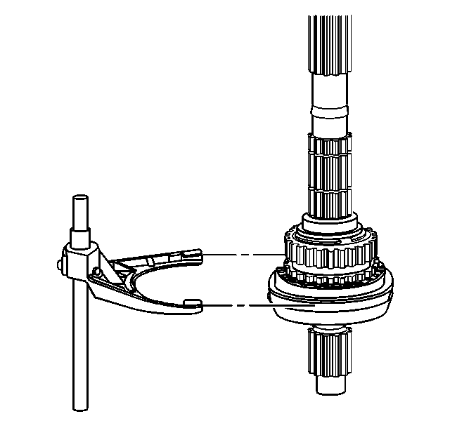
- Remove the mode fork from the rear output shaft.
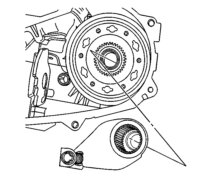
- Remove the low range fork
assembly.
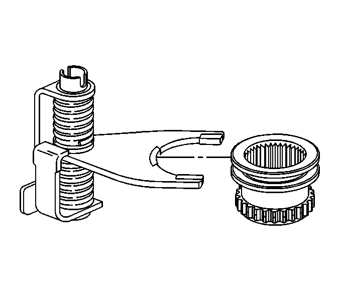
- Remove the range shift
sleeve.
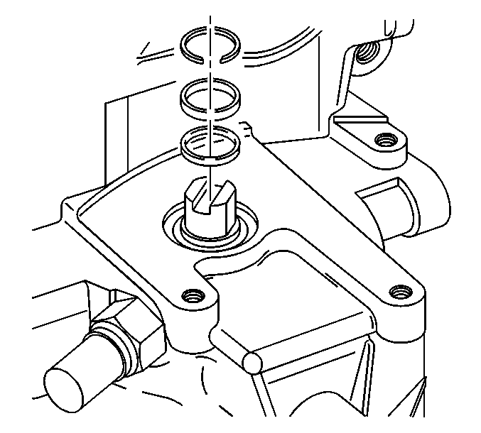
- Remove the sector shaft
retaining ring.
- Remove the sector shaft plastic sleeve.
- Remove the sector shaft O-ring.
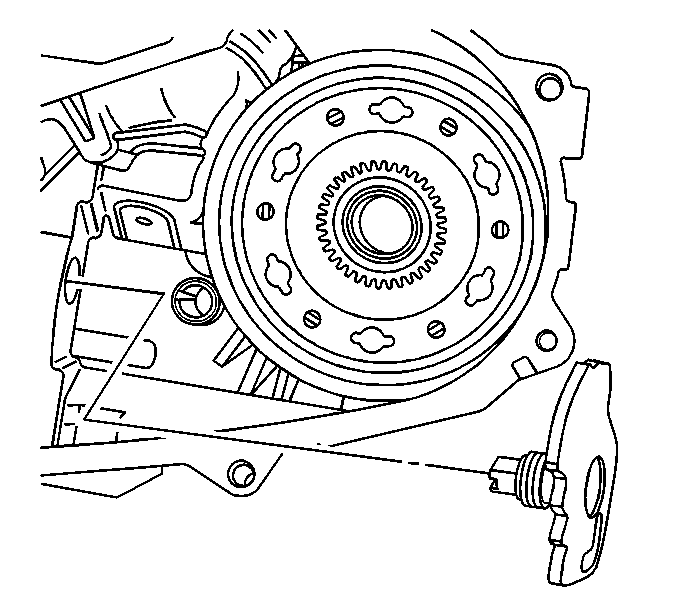
- Remove the sector shaft.
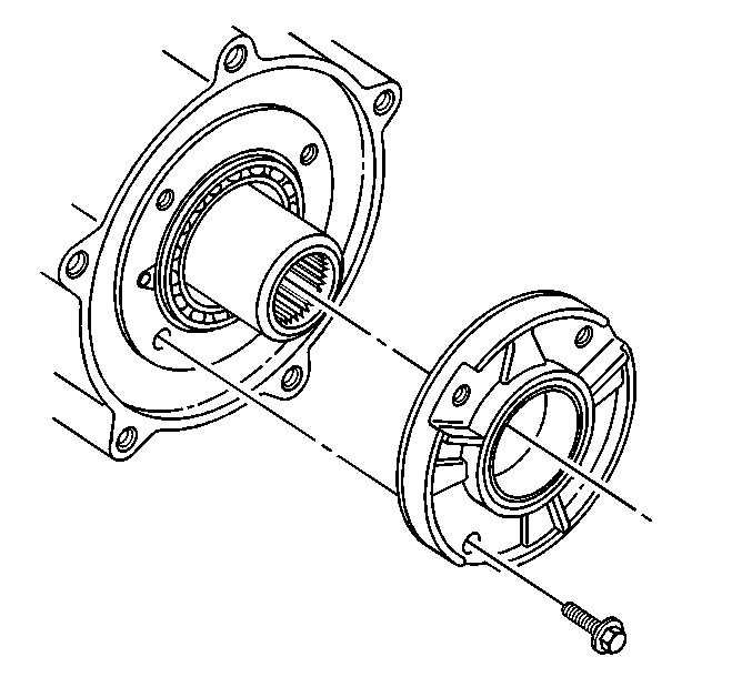
- Remove the input shaft
bearing retainer mounting bolts.
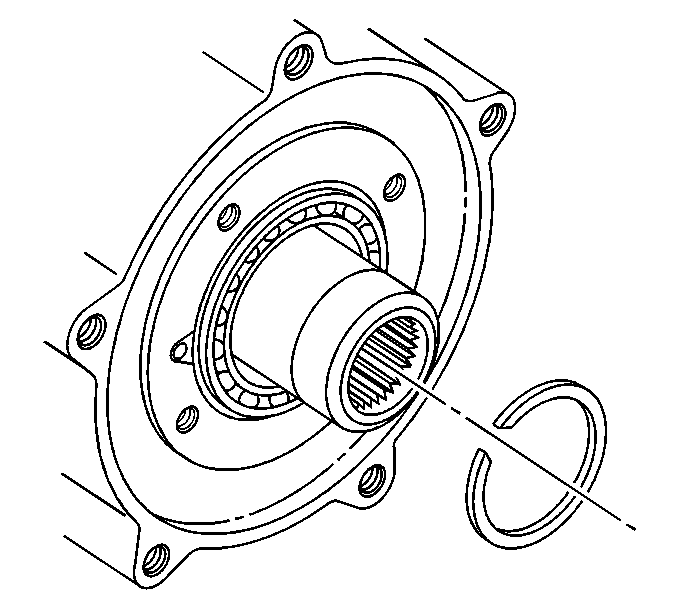
- Remove the input shaft
retaining ring.
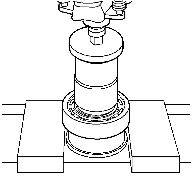
- Using the J 22912-B
, remove the input shaft bearing.
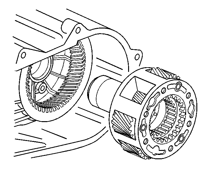
- Remove the planetary gear
assembly.
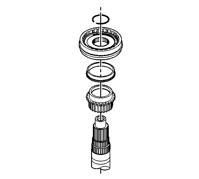
Important: It is not necessary to break down the synchronizer assembly into individual
pieces. If any part of the synchronizer assembly is found to be excessively
worn or damaged, replace the synchronizer as an assembly.
- Remove the synchronizer assembly retaining ring.
- Remove the synchronizer assembly.
- Remove the synchronizer ring.
- Remove the drive sprocket.
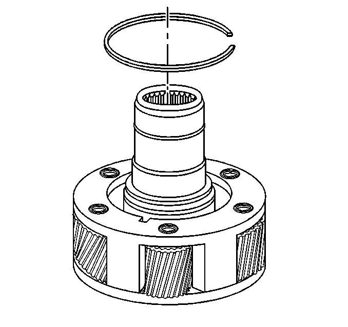
- Remove the input gear
retaining ring.
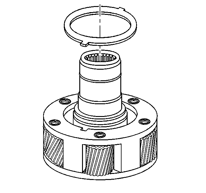
- Remove the thrust plate
from the planetary gear.
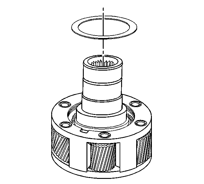
- Remove the thrust washer
from the planetary gear.
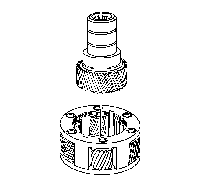
- Remove the input gear.
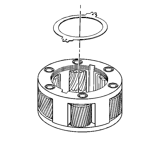
- Remove the thrust washer.
- Remove the input seal.
- Remove the output shaft seal.
- Using the J 29369
and the J 23907
,
remove the input gear pilot bearing.
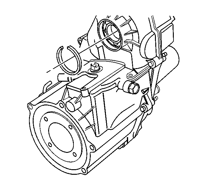
- Remove the front output
shaft retaining ring.
- Using the J 33790
and the J 8092
, remove
the front output shaft front bearing from the from case.
- Using the J 33790
and the J 8092
, remove
the output shaft rear bearing from the retainer.
- Using the J 33790
and the J 8092
, remove
the front input shaft bearing.


