Removal Procedure
Important: The upper intake does not have to be removed to remove the lower intake
manifold.
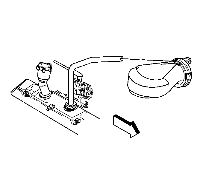
- Disconnect the breather
tube at the air cleaner outlet duct.
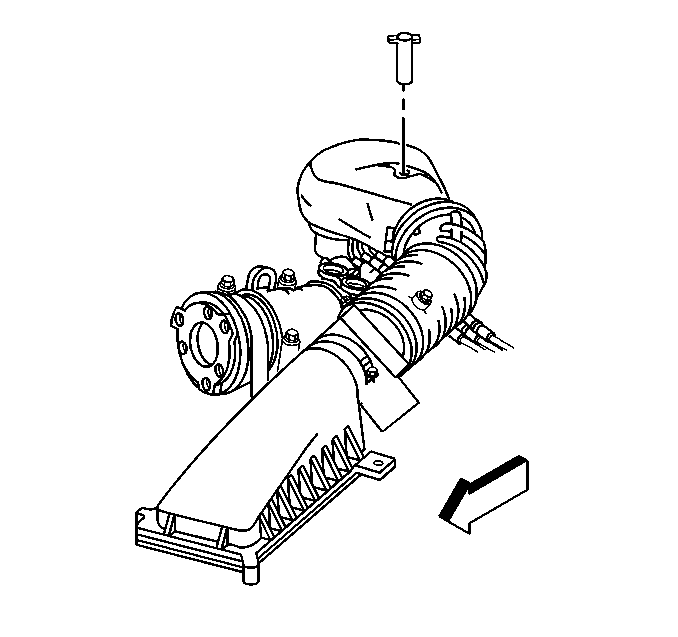
- Remove the air cleaner
outlet duct retaining wingnut.
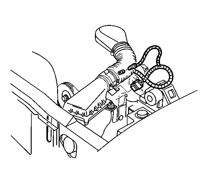
- Disconnect the IAT sensor
harness connector.
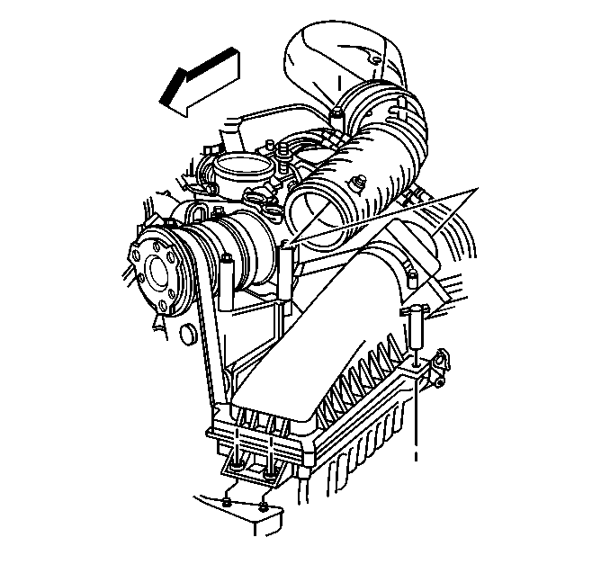
- Remove the air cleaner
outlet duct from the throttle body.
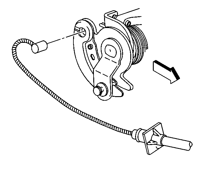
- Disconnect the accelerator
cable from the throttle body.
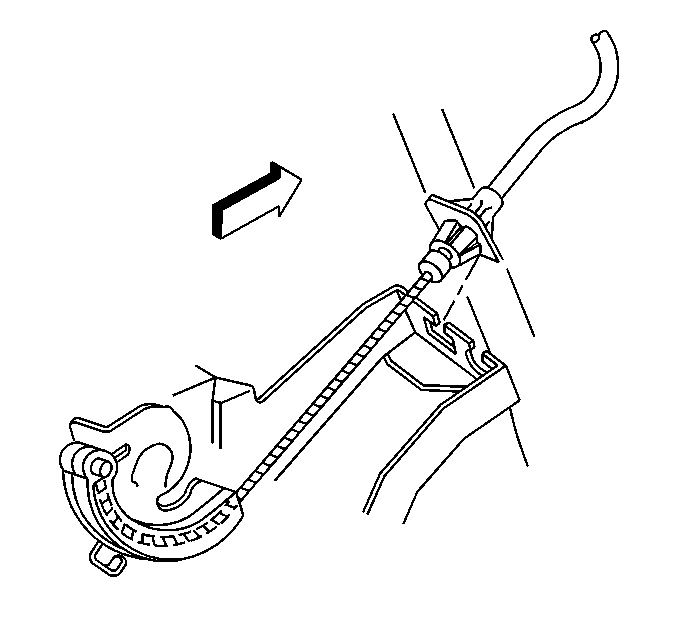
- Remove the accelerator
cable from the accelerator control cable bracket.
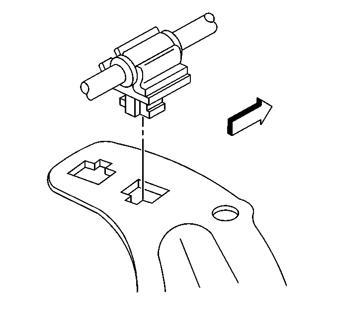
- Remove the accelerator
cable from the cable routing bracket.
- Disconnect the cruise control cable, if equipped from the throttle
shaft and the accelerator cable bracket. Refer to
Cruise Control Cable Replacement
in Cruise Control.
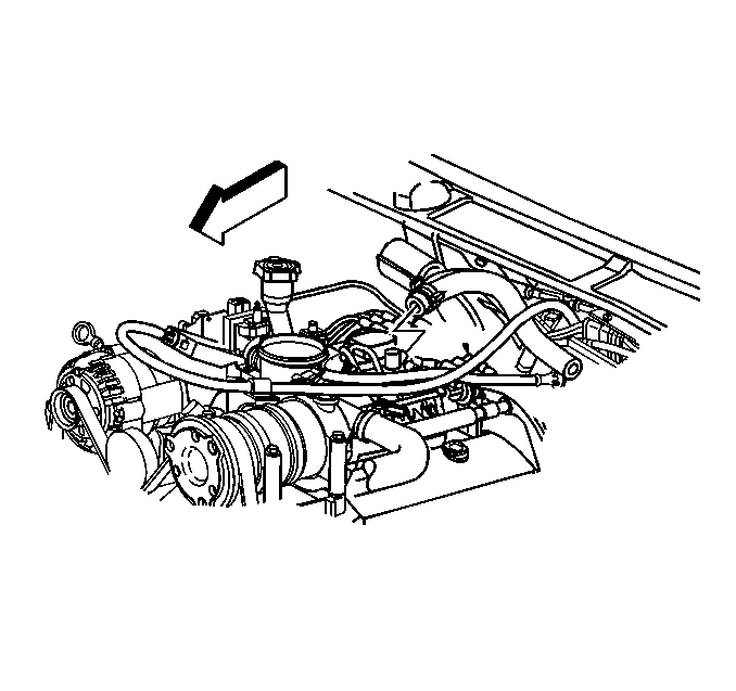
- Disconnect the vacuum
hose from the intake manifold for the vacuum tank.
- Remove the power brake booster vacuum hose.
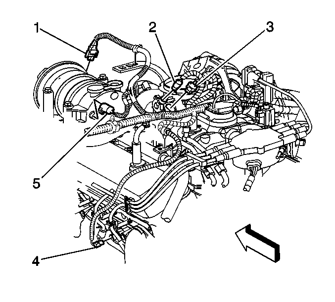
- Disconnect the following
electrical connectors:
| • | The A/C compressor clutch (1) |
| • | The A/C compressor cutoff switch (5), if equipped |
| • | The throttle position (TP) sensor (2) |
| • | The idle air control (IAC) motor (3) |
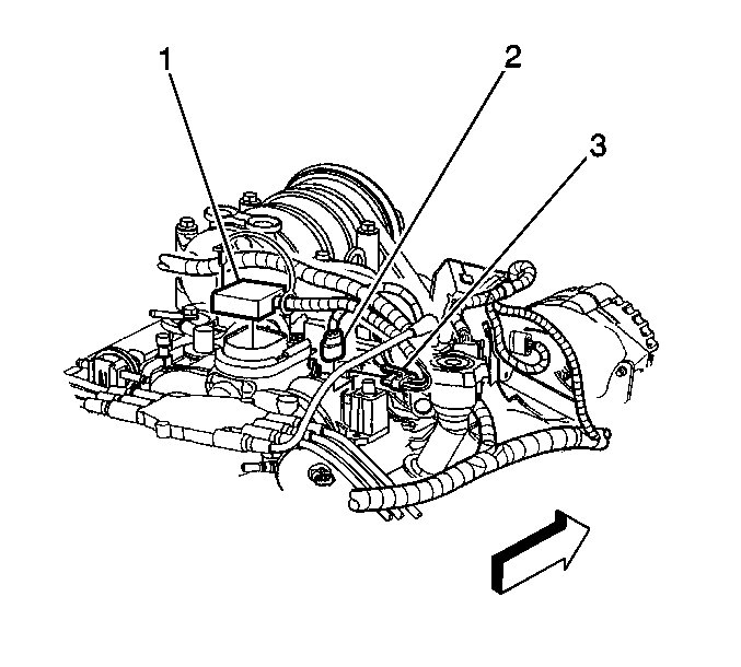
- Disconnect the following
electrical connectors:
| • | The fuel meter body assembly (1) |
| • | The manifold absolute pressure (MAP) sensor (3) |
| • | The EVAP canister purge solenoid valve (2) |
- Remove the engine wire harness clip from the accelerator cable
bracket.
- Move the engine wiring harness aside.
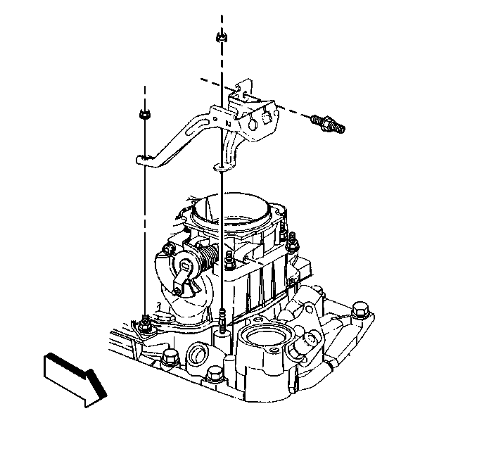
- Remove the accelerator
cable bracket from the throttle body and the intake manifold.
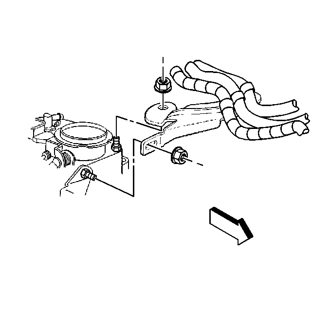
- Remove the accelerator
and cruise control cable bracket from the throttle body.
Leave the accelerator and cruise control cables on the bracket.
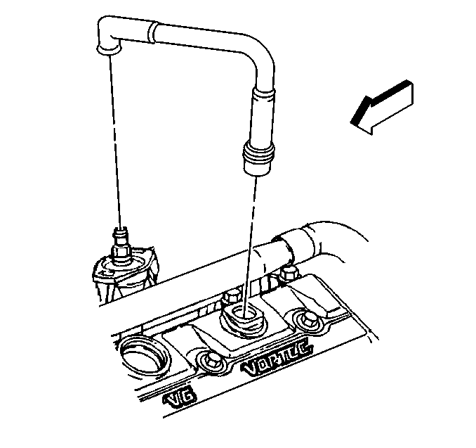
- Remove the PCV valve hose
assembly from the intake manifold and the valve rocker arm cover.
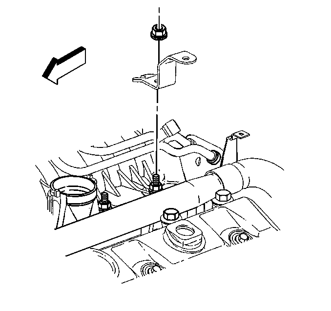
- Remove the bracket for
the engine wiring harness from the intake manifold stud.
- Remove the fuel lines from the fuel meter body assembly. Refer
to
Fuel Hose/Pipes Replacement - Engine Compartment
in Engine Controls - 4.3L.
- Remove the EVAP canister purge solenoid valve. Refer to
Evaporative Emission Canister Purge Solenoid Valve Replacement
in Engine Controls - 4.3L.
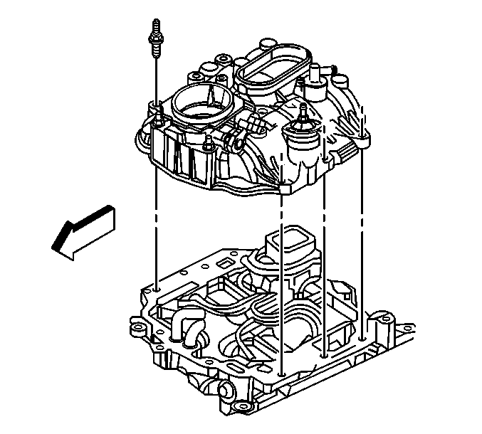
- Remove the studs for the
upper intake manifold.
- Remove the upper intake manifold.
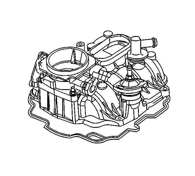
- Remove the upper intake
manifold gasket from the groove.
- Discard the gasket.
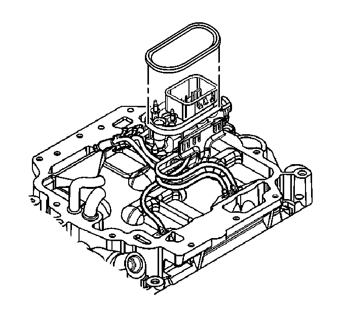
- Remove the seal from the
fuel meter body assembly.
- Discard the seal.
Important: Do not immerse the assembled upper intake manifold in cleaning solvent.
- Clean all sealing surfaces and the inside of the upper intake manifold
with a shop towel and cleaning solvent.
- Inspect the upper intake manifold for the following:
| • | Cracks or other damage to the exterior |
| • | Cracking or damage to the gasket grooves |
| • | Loose or damaged bolt hole thread inserts |
| • | Damage to the throttle body mounting surface |
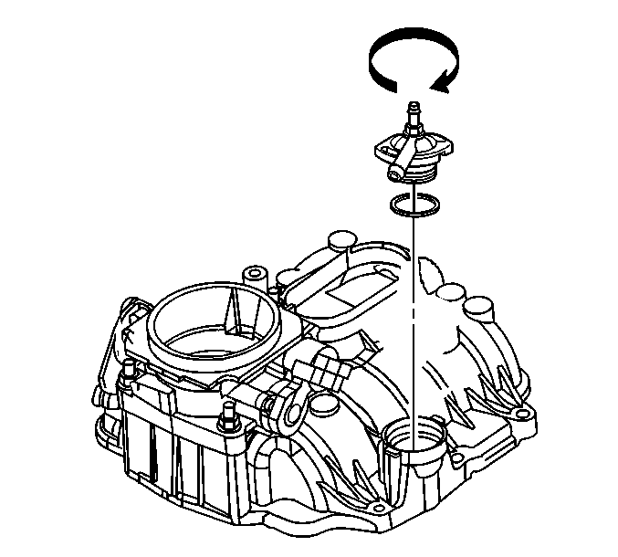
- If replacing the upper
intake manifold, turn and remove the power brake booster vacuum tube fitting
from the upper intake manifold.
- Remove and discard the seal.
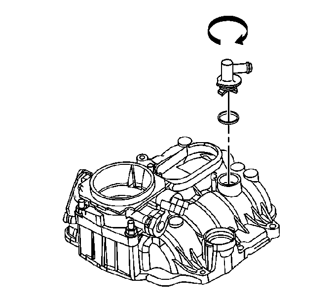
- If replacing the upper
intake manifold, turn and remove the PCV valve cover from the upper intake
manifold.
- Remove and discard the seal.
- Remove the throttle body if replacing the upper intake manifold.
Refer to
Throttle Body Assembly Replacement
in Engine Controls - 4.3L.
- Remove the MAP sensor if replacing the upper intake manifold.
Refer to
Manifold Absolute Pressure Sensor Replacement
in Engine Controls - 4.3L.
Installation Procedure

- Install the throttle body,
if removed. Refer to
Throttle Body Assembly Replacement
in Engine Controls - 4.3L.
- Install the MAP sensor, if removed. Refer to
Manifold Absolute Pressure Sensor Replacement
in Engine Controls
- 4.3L.
- Install the PCV valve cover, if removed, using the following procedure:
| 3.1. | Install a NEW seal (O-ring) on the PCV valve cover. |
| 3.2. | Lubricate the seal with clean engine oil. |
| 3.3. | Install the PCV valve cover in the upper intake manifold. |
| 3.4. | Turn and lock the PCV valve cover in position. |

- Install the power brake
booster vacuum tube fitting, if removed, using the following procedure:
| 4.1. | Install a NEW seal (O-ring) on the power brake booster vacuum
tube fitting. |
| 4.2. | Lubricate the seal with clean engine oil. |
| 4.3. | Install the power brake booster vacuum tube fitting in the upper
intake manifold. |
| 4.4. | Turn and lock the power brake booster vacuum tube fitting in
position. |

- Install a NEW seal on
the fuel meter body assembly.
- Lubricate the seal with clean engine oil.

- Install a NEW upper intake
manifold to lower intake manifold gasket in the groove of the upper intake
manifold.

- Install the upper intake
manifold onto the lower intake manifold.
- If reusing the fasteners, apply threadlock GM P/N 12345382
or equivalent to the threads of the upper intake manifold attaching bolts.
Notice: Use the correct fastener in the correct location. Replacement fasteners
must be the correct part number for that application. Fasteners requiring
replacement or fasteners requiring the use of thread locking compound or sealant
are identified in the service procedure. Do not use paints, lubricants, or
corrosion inhibitors on fasteners or fastener joint surfaces unless specified.
These coatings affect fastener torque and joint clamping force and may damage
the fastener. Use the correct tightening sequence and specifications when
installing fasteners in order to avoid damage to parts and systems.
- Install the upper
intake manifold attaching studs.
Tighten
- Tighten the upper intake manifold attaching studs on the first
pass to 5 N·m (44 lb in).
- Tighten the upper intake manifold attaching studs on the final
pass to 9 N·m (80 lb in).
- Install the fuel lines to the fuel meter body assembly. Refer
to
Fuel Hose/Pipes Replacement - Engine Compartment
in Engine Controls - 4.3L.
- Install the EVAP canister purge solenoid valve. Refer to
Evaporative Emission Canister Purge Solenoid Valve Replacement
in Engine Controls - 4.3L.

- Install the bracket for
the engine wiring harness on the lower intake manifold stud.
- Install the engine wiring harness bracket nut.
Tighten
Tighten the engine wiring harness bracket nut to 12 N·m
(106 lb in).

- Install the accelerator
and cruise control cable bracket to the throttle body.
- Install the accelerator and cruise control cable bracket nuts.
Tighten
Tighten the accelerator and cruise control cable bracket nuts to 9 N·m
(80 lb in).

- Install the accelerator
control cable bracket to the throttle body and the intake manifold.
Tighten
Tighten the accelerator control cable bracket studs and nuts to 12 N·m
(106 lb in).

- Connect the PCV valve
hose assembly to the intake manifold and the valve rocker arm cover.

- Position the engine wiring
harness.
- Install the wire harness clip to the accelerator cable bracket.
- Connect the following electrical connectors:
| • | The fuel meter body assembly (1) |
| • | The manifold absolute pressure (MAP) sensor (3) |
| • | The EVAP canister purge solenoid valve (2) |

- Connect the following
electrical connectors:
| • | The A/C compressor clutch (1) |
| • | The A/C compressor cutoff switch (5), if equipped |
| • | The throttle position (TP) sensor (2) |
| • | The idle air control (IAC) motor (3) |

- Connect the vacuum hose
from the vacuum tank to the intake manifold.
- Install the power brake booster vacuum hose to the intake manifold.
- Install the cruise control cable, if equipped to the throttle
shaft and the bracket. Refer to
Cruise Control Cable Replacement
in Cruise Control.

- Install the accelerator
cable onto the throttle body.
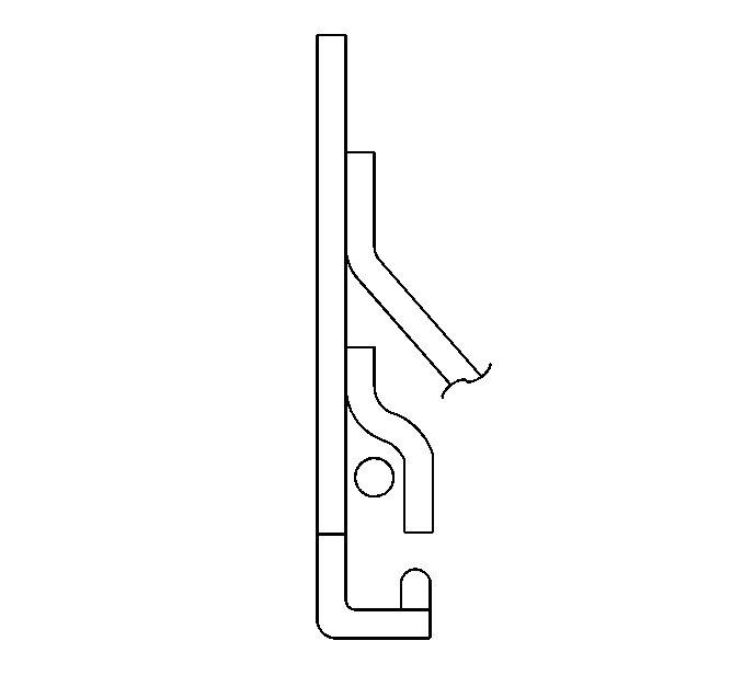
- Wrap the cable in between
the finger of the hook tab and the pulley wall. Make sure that the cable is
fully seated in the pulley groove. The cable must not lie outside of the
hook tab.

- Install the accelerator
cable to the accelerator cable control bracket.

- Install the accelerator
cable to the cable routing bracket.
Notice:
| • | Handle the MAF sensor carefully. |
| • | Do not drop the MAF sensor in order to prevent damage to the MAF
sensor. |
| • | Do not damage the screen located on the air inlet
end of the MAF. |
| • | Do not touch the sensing elements. |
| • | Do not allow solvents and lubricants to come in contact with the
sensing elements. |
| • | Use a small amount of a soap based solution in order to aid in
the installation. |

- Install air cleaner outlet
duct to throttle body.
- Install air cleaner outlet duct to MAF sensor.
Tighten
Tighten the hose clamp to 4 N·m (32 lb in).

- Connect the IAT sensor
harness connector.

- Install the air cleaner
outlet duct retaining wingnut.
Tighten
Tighten the wingnut to 2 N·m (18 lb in).

- Connect the breather tube
to the air cleaner outlet duct.


