Tools Required
J 21854-01 Pivot Pin Remover
Removal Procedure
- Disable the SIR system. Refer to SIR Disabling and Enabling in SIR.
- Remove the signal switch housing assembly. Refer to Turn Signal Switch Housing Replacement .
- Remove the lock cylinder housing assembly, the ignition switch assembly, and the BTSI assembly only. Refer to Lock Module Replacement .
- Remove the tilt spring only. Refer to Steering Column Tilt Spring Replacement .
- Remove the steering column wire harness assembly only. Refer to Steering Column Wiring Harness Assembly Replacement .
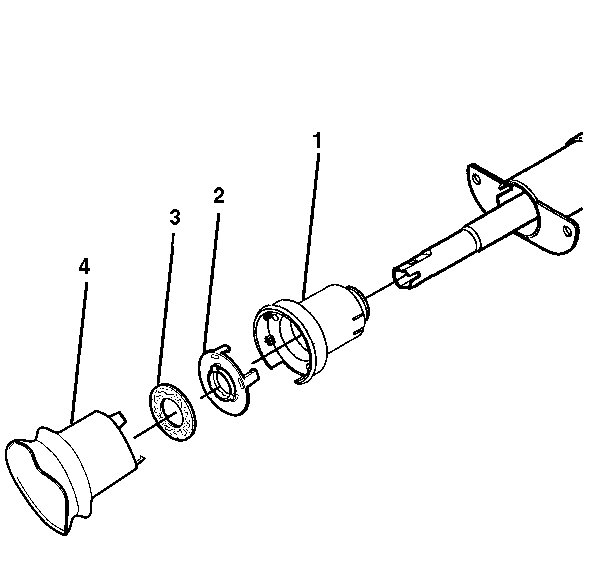
- Remove the inner boot seal (4).
- Remove the steering shaft seal (3).
- Remove the sensor retainer (2).
- Remove the adapter and bearing assembly (1).
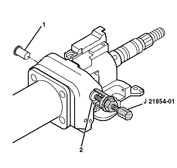
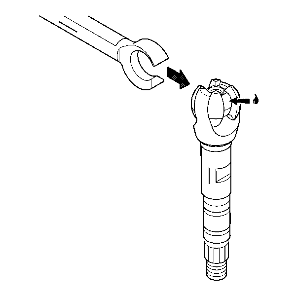
- Remove the 2 pivot pins (1,2) using J 21854-01 .
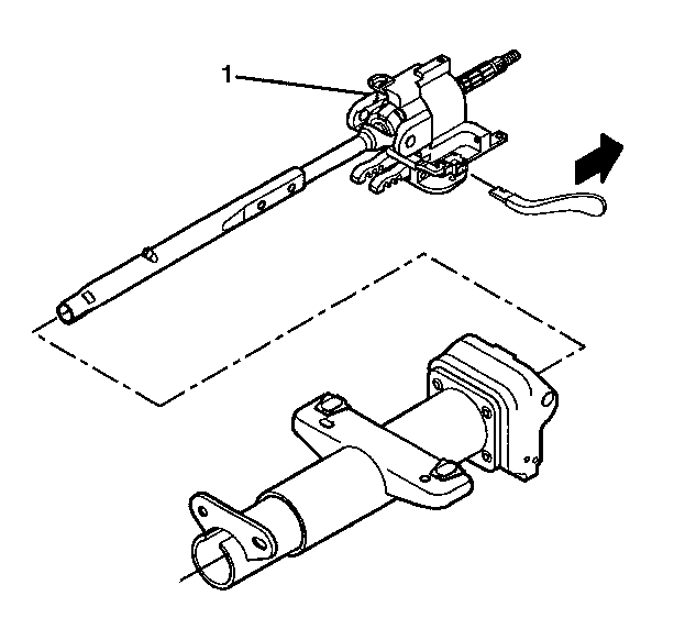
- Install the tilt lever.
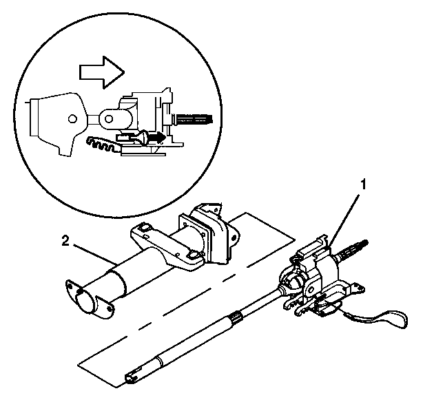
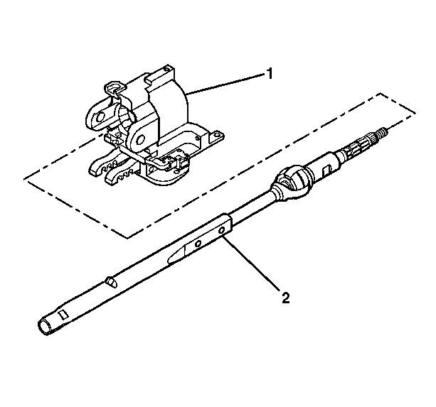
- Pull back on the tilt lever to disengage the steering wheel lock shoes. Remove the tilt head assembly (1) with the shaft assembly from the steering column jacket assembly (2).
- Remove the steering shaft assembly (2) from the tilt head assembly (1).
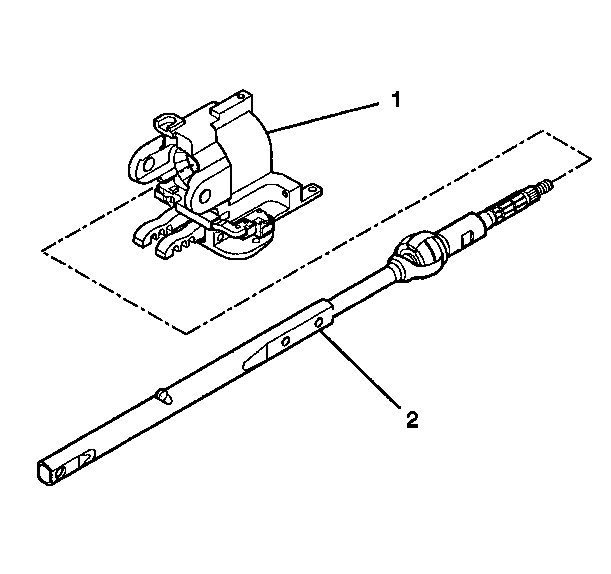
- Tilt the race and the upper shaft assembly (1) 90 degrees to the lower shaft assembly (2).
- Disengage the race and the upper shaft assembly (1) from the lower shaft assembly (2).
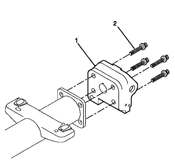
- Remove and discard the 4 TORX® head screws (2) from the steering column support assembly (1).
- Remove the steering column support assembly (1).
Caution: Refer to SIR Caution in the Preface section.
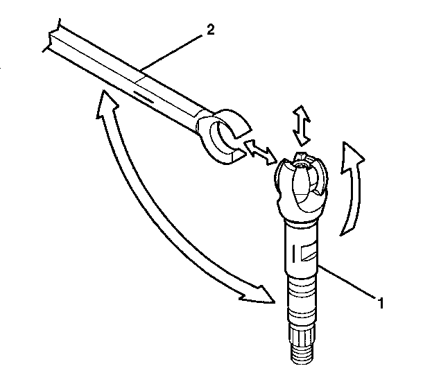
Important: Mark the race and upper shaft assembly and the lower shaft assembly before disassembly. Failure to assemble the race and upper shaft assembly and the lower shaft assembly correctly will cause the steering wheel to be turned 180 degrees.
Installation Procedure
- Attach the steering column support assembly (1) to the jacket assembly with 4 new TORX® head screws (2).
- Apply GM P/N 12345718 (Canadian P/N 10953516) to the exposed steering shaft.
- Align the lower steering shaft assembly at 90 degrees to the race and upper shaft assembly.
- Install the lower steering shaft assembly onto the race and upper shaft assembly.
- Install the steering shaft assembly (2) into the tilt head assembly (1).
- Install the steering shaft assembly with the tilt head assembly (1) into the steering column support assembly.
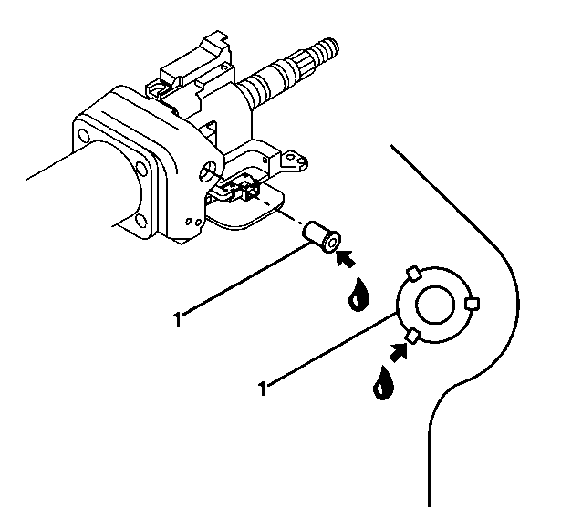
- Lubricate the pivot pins (1) with GM P/N 12346293 (Canadian P/N 992723).
- Firmly seat each pivot pin (1) into the tilt head assembly.
- Stake the pivot pins (1).
- Install the following items to the steering column jacket assembly:
- Install the steering column wire harness assembly only. Refer to Steering Column Wiring Harness Assembly Replacement .
- Install the tilt spring only. Refer to Steering Column Tilt Spring Replacement .
- Install the lock cylinder housing, the ignition switch assembly, and the A/T shift lock control solenoid assembly only. Refer to Lock Module Replacement .
- Install the turn signal switch housing. Refer to Turn Signal Switch Housing Replacement .
- Enable the SIR system. Refer to SIR Disabling and Enabling in SIR.

Important: Replace the steering column support assembly (1) if the steering column support assembly has been staked 3 times.
Notice: Use the correct fastener in the correct location. Replacement fasteners must be the correct part number for that application. Fasteners requiring replacement or fasteners requiring the use of thread locking compound or sealant are identified in the service procedure. Do not use paints, lubricants, or corrosion inhibitors on fasteners or fastener joint surfaces unless specified. These coatings affect fastener torque and joint clamping force and may damage the fastener. Use the correct tightening sequence and specifications when installing fasteners in order to avoid damage to parts and systems.
Tighten
Tighten the screws to 17 N·m (13 lb ft).

| 10.1. | The adapter and bearing assembly (1) |
| 10.2. | The sensor retainer (2) |
| 10.3. | The steering shaft seal (3) |
| 10.4. | The inner boot seal (4) |
Caution: Improper routing of the wire harness assembly may damage the inflatable restraint steering wheel module coil. This may result in a malfunction of the coil, which may cause personal injury.
