Tools Required
J 22536 Pinion Driver
Removal Procedure
- Raise the vehicle. Refer to Lifting and Jacking the Vehicle in General Information.
- Remove the tire and wheel assemblies. Refer to Tire and Wheel Removal and Installation in Tires and Wheels.
- Remove the brake calipers. Refer to Rear Brake Caliper Replacement in Disc Brakes.
- Remove the brake rotors. Refer to Rear Brake Rotor Replacement in Disc Brakes.
- Remove the axle shafts. Refer to Rear Axle Shaft Replacement .
- Remove the differential. Refer to Differential Replacement .
- Remove the drive pinion yoke and the seal. Refer to Drive Pinion Flange/Yoke and/or Oil Seal Replacement .
- Install the J 22536 as shown.
- Drive the pinion out using the J 22536 and a hammer.
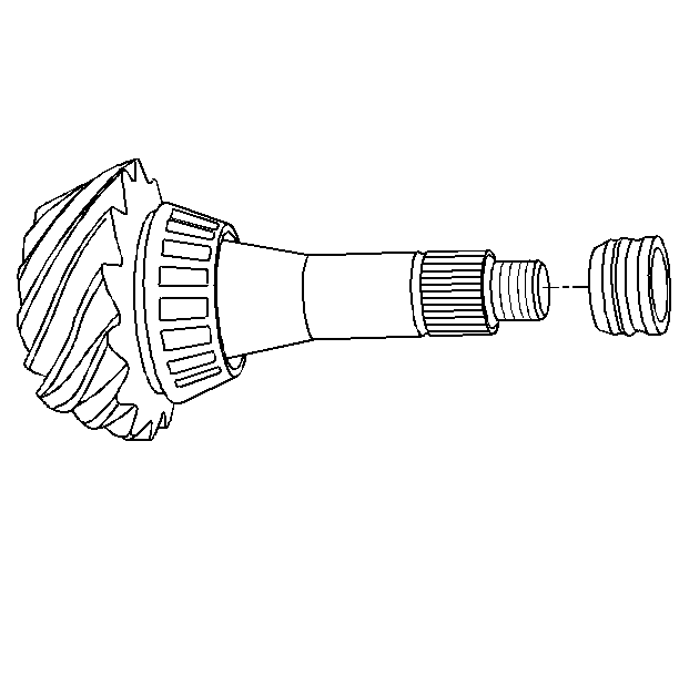
- Remove the collapsible spacer from the pinion. Discard the spacer.
- Remove the pinion bearings and the cups. Refer to Drive Pinion Bearings Replacement .
- Remove the left handed threaded ring gear bolts. Discard the bolts.
- Remove the ring gear from the differential. Drive the gear off with a brass drift if necessary.
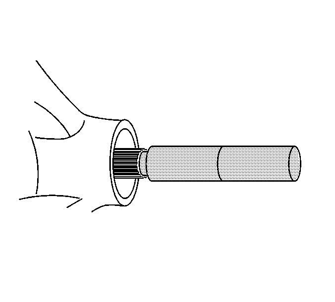
Ensure that the J 22536 is firmly seated on the pinion.
Strike the J 22536 slowly. Do not let the pinion fall out of the rear axle housing.
Installation Procedure
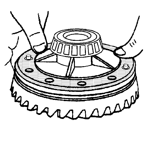
- Install the ring gear to the differential case.
- Install the new ring gear bolts. Tighten the ring gear bolts alternately and in stages, gradually pulling the ring gear onto the differential case.
- Install the pinion bearing cups. Refer to Drive Pinion Bearings Replacement .
- Determine the selective shim thickness for the pinion gear. Refer to Pinion Depth Adjustment .
- Install the selective shim onto the pinion.
- Install the inner pinion bearing to the pinion. Refer to Drive Pinion Bearings Replacement .
- Install a new collapsible spacer.
- Lubricate the pinion bearings with axle lubricant. Refer to Fluid and Lubricant Recommendations in Maintenance and Lubrication.
- Install the pinion to the axle housing.
- Install the outer pinion bearing.
- Install a new pinion oil seal and the pinion yoke. Refer to Drive Pinion Flange/Yoke and/or Oil Seal Replacement .
- Install the differential. Refer to Differential Replacement .
- Perform a gear tooth contact pattern check on the pinion and the ring gear. Refer to Gear Tooth Contact Pattern Inspection .
- Install the axle shafts. Refer to Rear Axle Shaft Replacement .
- Install the brake rotors. Refer to Rear Brake Rotor Replacement in Disc Brakes.
- Install the brake calipers. Refer to Rear Brake Caliper Replacement in Disc Brakes.
- Install the tire and wheel assemblies. Refer to Tire and Wheel Removal and Installation in Tires and Wheels.
- Fill the axle with lubricant. Use the proper fluid. Refer to Fluid and Lubricant Recommendations and Approximate Fluid Capacities in Maintenance and Lubrication.
- Lower the vehicle.
Important: The mating surface of the ring gear and the differential case must be clean and free of burrs before installing the ring gear.
Notice: Use the correct fastener in the correct location. Replacement fasteners must be the correct part number for that application. Fasteners requiring replacement or fasteners requiring the use of thread locking compound or sealant are identified in the service procedure. Do not use paints, lubricants, or corrosion inhibitors on fasteners or fastener joint surfaces unless specified. These coatings affect fastener torque and joint clamping force and may damage the fastener. Use the correct tightening sequence and specifications when installing fasteners in order to avoid damage to parts and systems.
Tighten
Tighten the ring gear bolts in sequence to 100 N·m (74 lb ft).
