COMPARTMENT LIFT WINDOW GLASS REPLACEMENT AND ADJUSTMENT

Subject: COMPARTMENT LIFT WINDOW GLASS REPLACEMENT & ADJUSTMENT 1982 "F" SERIES - INITIATED BY FISHER BODY (NEW SERVICE PROCEDURE)
CAUTION:
When working with glass assemblies, the use of personal protection items, such as work gloves and eye protection, is recommended to reduce the chance of personal injury should the glass break.
REMOVAL PROCEDURE
1. Place protective covering along edges of rear compartment to prevent damage to painted surfaces.
2. If glass is broken, clean all broken glass from interior of vehicle.
3. From inside of car, remove plastic covers from bolts for gas supports to body.
4. If equipped with heated back glass, remove wire connectors from gas supports.
a. Unlock rear compartment lift window. b. Have helper support lid in partially open position.
5. Remove:
a. Bolts holding gas supports to body. b. Back body opening upper garnish molding. c. Nuts retaining lift window hinge to body.
6. With aid of helper, remove lift window from car and place upside down on a protected surface. Note position of hinge shims (if present).
7. Remove:
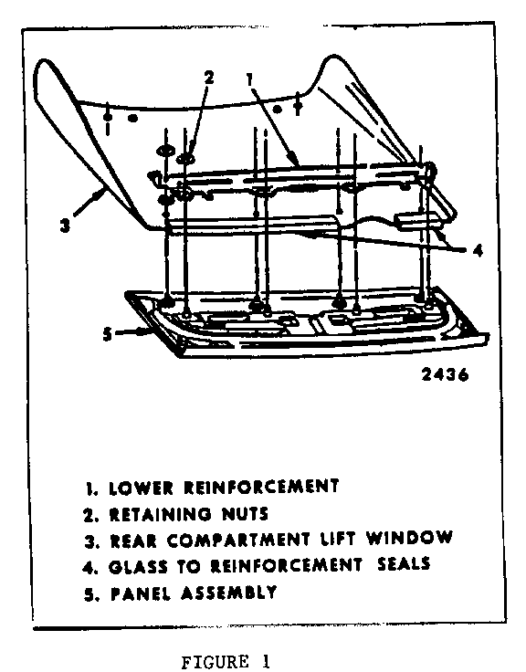
a. Gas supports from lower reinforcement. b. Hinge assemblies from glass. c. Trim panel. d. Wiper and blade assembly (if present). e. Lock striker. f. Electrical contact and wiring harness (if present). 9. Lower reinforcement (Figure 7-4, Item #1). h. Screws holding glass finishing molding to panel. i. Nylon patches at radius joint of panel by cutting through adhesive using a curved blade utility knife.
8. With aid of helper, turn lift window over and place masking tape along top edge of panel.
a. If glass is being replaced for any reason other than breakage, use a flat-bladed sharp tool to cut out foam and butyl sealing strips between panel and glass. Clean tool frequently to ease cutting operation. b. Lift upward on panel and pull from glass being careful not to distort ends of glass molding.
9. Clean panel of foam sealing strip and all adhesives. This can be done by using a cloth dampened in alcohol.
10. Remove lower glass sealing strips (Figure 7-5, Item #5).
11. Remove and discard plastic spacers.
INSTALLATION
1. If a new glass is to be installed, new glass finishing moldings will be required. To install molding to glass:
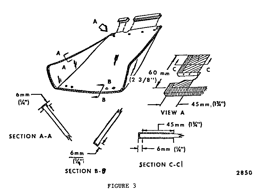
a. Use clear primer in urethane kit 9636067. Apply primer to glass as shown in Figure 3.
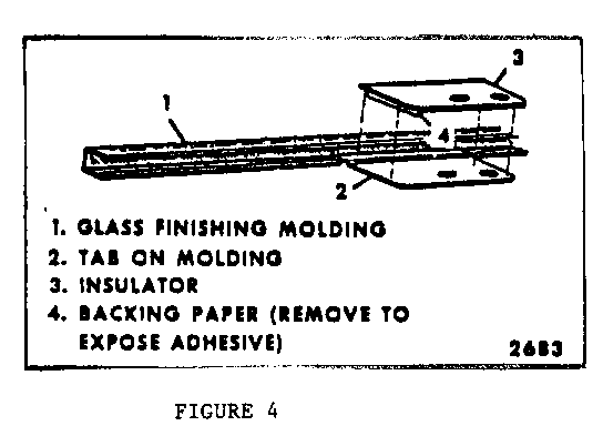
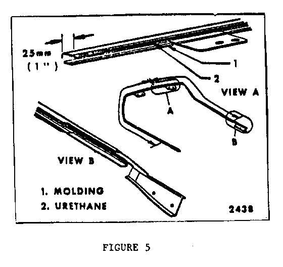
b. Install right and left hand gaskets to tabs on glass molding as shown in Figure 7-8, align holes in gaskets to holes in molding tabs.
c. Apply a 4.5mm or 3/16" bead of urethane from kit into molding channel as shown in Figure 7-7. Do not apply urethane for a distance of 25mm or 1" from center end of each molding.
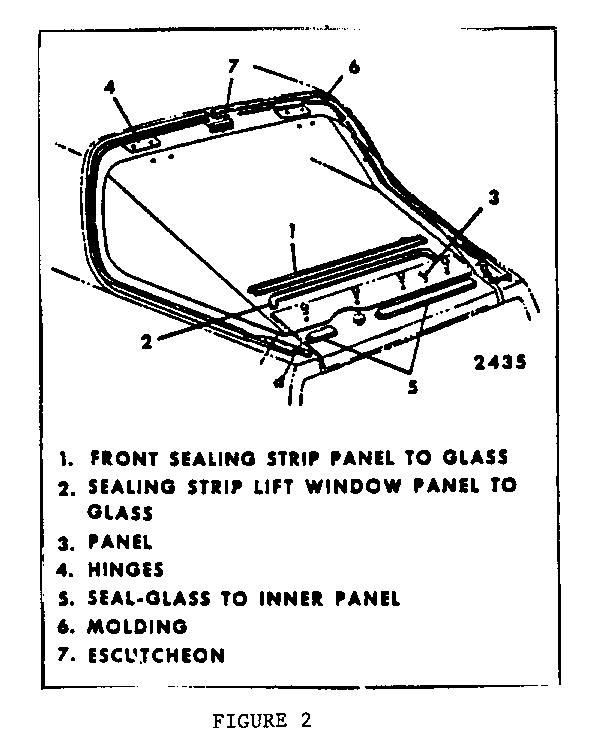
d. Place molding escutcheon inside right and left hand moldings (Figure 2, Item #7).
Use a rubber mallet, install moldings onto glass making sure to align holes in tabs of molding with holes in glass. Be sure corner area is fully seated.
CAUTION:
When performing next operations, do not tighten beyond specified torque or glass breakage and personal injury could result.
2. Install hinge to glass; torque bolts 16 N.m (11 ft. lbs.).
3. Install the following items:
a. Glass to reinforcement seals to read edge of glass (Figure 1, Item #4).
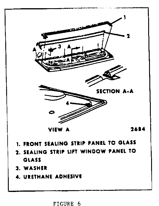
b. Front sealing strip (P/N 20328200), Figure 6, Item #1.
c. Butyl adhesive strip (5/16 square), 3M - P/N 08631, next to sealing strip, Figure 6, Item #2. Seal holes in panel where glass molding screws were installed using above butyl.
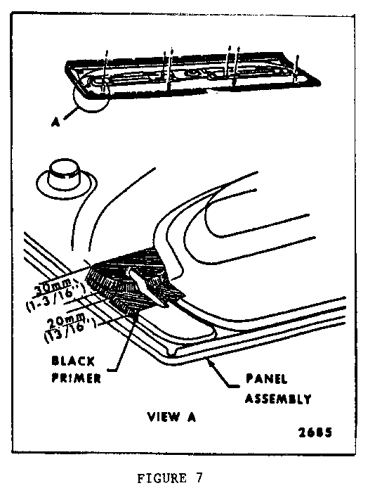
d. Apply black primer (from kit) to panel, Figure 7. Allow to air dry for five (5) minutes.
e. Apply urethane (P/N 9636067) to area of panel primed in above step. Smooth urethane with a flat bladed tool. If new panel is to be installed, also apply to forward outer drain holes (Figure 7, View A).
4) Install panel to glass.
a. Place new glass spacers over forward studs on panel (if original glass was broken), Figure 6, Item #3).
b. Place glass on panel by placing holes in glass over studs on panel. Align panel to glass in rear most position.
c. Place spacers between glass and lower reinforcement.
d. Place lower reinforcement over studs on panel (Figure 1, Item #1).
e. Apply nylon patches to glass (being sure of right and left hand part installation).
f. Hand tighten all nuts retaining the reinforcement to panel.
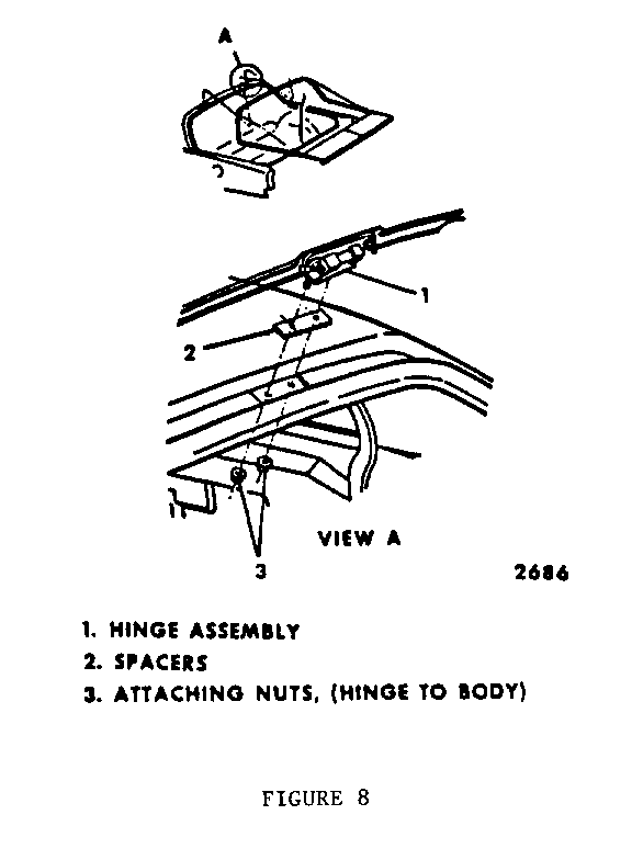
g. With the aid of a helper, install rear compartment lift window assembly to the body. If the glass needs adjustment to the body, the holes for the hinge body bolts are oversized which allows for some adjustment. Install original hinge shims to body. Once the glass is properly aligned, torque hinge to body bolts to 20-28 N.m or 15-20 ft. lbs. (Figure 8).
h. From inside the car, loosen the lower reinforcement to panel nuts.
i. From outside the car, position rear panel centered and forward 3mm or 1/8" of final desired position.
j. From inside the car, hand tighten the lower reinforcement to panel nuts.
k. Raise and prop open rear compartment lift window.
CAUTION:
When performing next operations, do not tighten beyond specified torque or glass breakage and personal injury could result.
l. Tighten retaining nuts to 16 N.m or (11 ft. lbs.) in the following order:
o forward center o rear center o all remaining nuts
m. Install screws securing glass finishing molding to panel. It may be necessary to drill two (2) small holes in panel for molding retaining screws.
5. While helper supports lift window, install gas supports to body. Be sure that electrical contact at forward edge of gas support (if present) is inboard, then:
a. Torque gas support to body bolts to 20-28 N.m or 15-20 ft. lbs.
b. Torque gas support to lift window bolts 5-7 N.m (40-60 in. lbs.).
c. Reinstall wiring harness and upper electrical contact to lift window panel (if present).
d. Install wiper motor to lift window (if present) torque all bolts 5-7 N.m (40-60 in. lbs.).
e. Install lock striker to lift window panel and carefully check lock striker to lock engagement.
f. If it is necessary to adjust lock for proper engagement of striker, remove rear end trim panel.
g. Loosen bolts holding lock to rear end panel (and solenoid if present).
h. Adjust lock for proper engagement of striker.
i. Tighten all bolts to torque of 9-12 N.m (60-80 in. lbs.).
j. Install trim previously removed.
General Motors bulletins are intended for use by professional technicians, not a "do-it-yourselfer". They are written to inform those technicians of conditions that may occur on some vehicles, or to provide information that could assist in the proper service of a vehicle. Properly trained technicians have the equipment, tools, safety instructions and know-how to do a job properly and safely. If a condition is described, do not assume that the bulletin applies to your vehicle, or that your vehicle will have that condition. See a General Motors dealer servicing your brand of General Motors vehicle for information on whether your vehicle may benefit from the information.
