CANISTER CONTROL VALVE CODE 45 REVISED MOUNTING PROCEDURE

In the event a canister control valve requires replacement, refer to Chevrolet Service Bulletin 83-I-29 for functional testing. A new part number valve should be installed (refer to chart below). In addition, on all vehicles the valve should be suspended using the following procedure:
ENGINE ENGINE VIN VIN CODE CODE DIS- PLACE- ENGINE/ NEW CCV MENT VEHICLE VALVE MOUNT PART NO. 1982 1983
1982/ 5.7L LM1 Suspend 17075074 83 No Sketch Needed L 6
1982/ 5.0L LG4 Suspend 17075074 H 83 "B" & "G" No Sketch Needed
1982/ 5.0L LG4/"F" Suspend Per 17075074 H H 83 LG4 With 7K4 Sketch #1 "B" & "G"
1982 3.8L LC3/"B" Suspend Per 17075075 K LC3/"G" Sketch #2 17075074 K
1983 3.8L LC3/"B" Suspend Per 17075075 9 LC3/"G" Sketch #3 17075074 9
1982 4.4L L39 Suspend 17075074 J "B" & "G" No Sketch Needed
VALVE MOUNTING INSTRUCTIONS
I. 1982-1983 LG4-LM1 in "B" or "G" Vehicles 1982 L39 in "B" or "G" Vehicles
1. Remove bolt which retains CCV bracket to alternator brace and discard.
2. Remove two (2) screws which retain CCV to bracket.Discard bracket and screws.
3. Allow CCV to be suspended in hose harness.
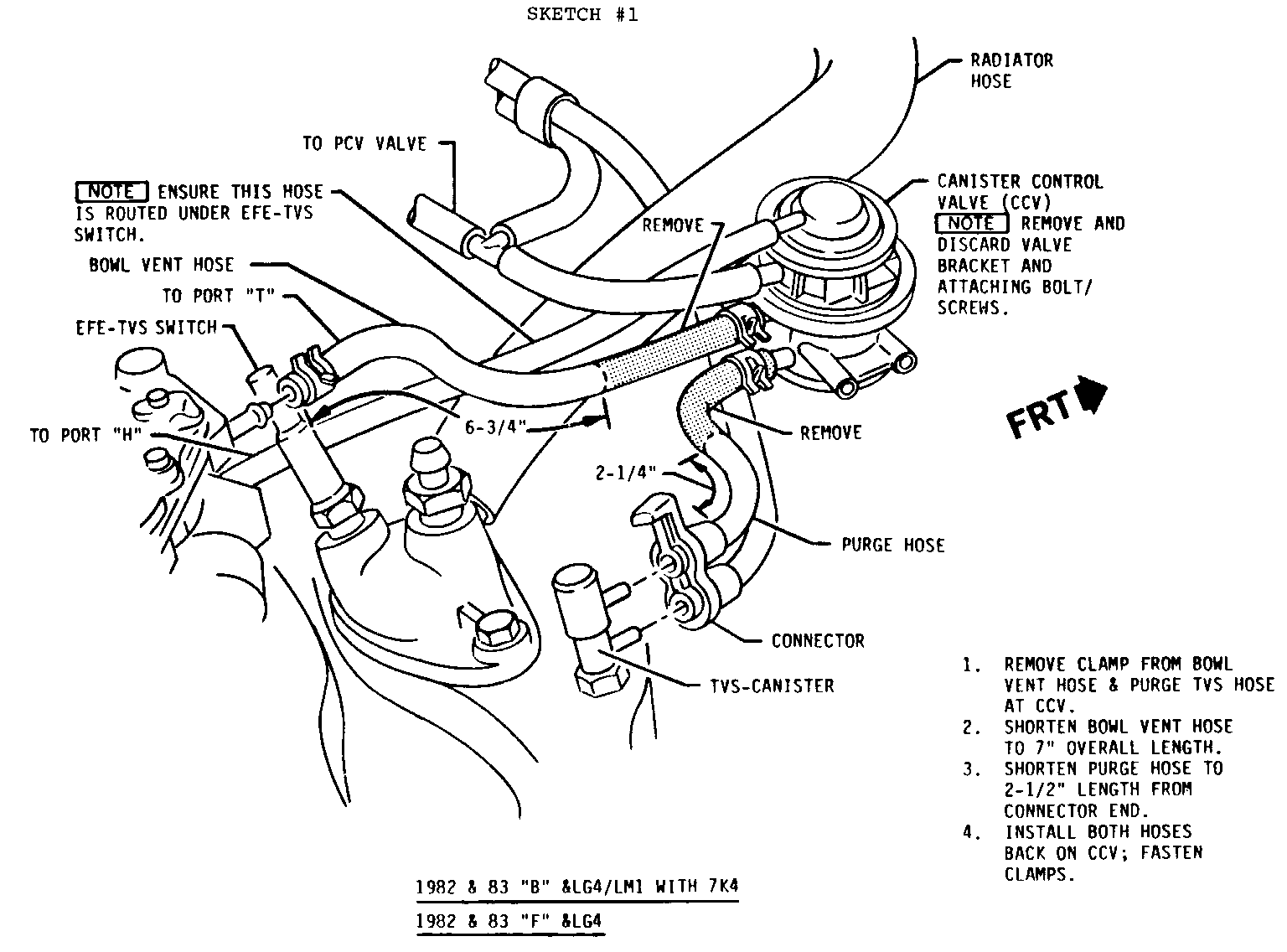
II. 1982-83 "B" or "G" and LG4/LM1 With 7K4 1982-83 "F" and LG4 (refer to Sketch #1)
1. Remove bolt which retains CCV bracket to alternator brace and discard.
2. Remove two (2) screws which retain CCV to bracket. Discard bracket and screws.
3. Remove clamp from bowl vent hose and purge TVS hose at CCV.
4. Shorten bowl vent hose to 6 3/4" overall length.
5. Shorten purge hose to 2 1/4" length from connector end.
6. Install both hoses back on CCV; fasten clamps.
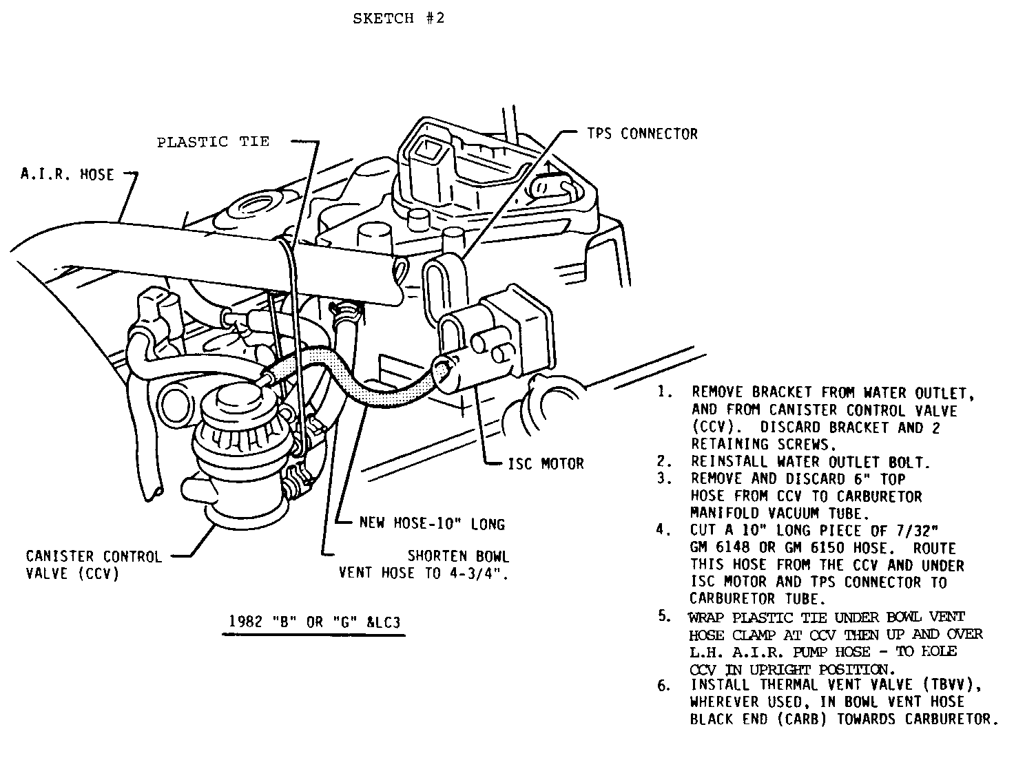
III.1982 "B" or "G" and LC3 (refer to Sketch #2)
1. Remove bracket from water outlet and from canister control valve (CCV). Discard bracket and two (2) retaining screws.
2. Reinstall water outlet bolt.
3. Shorten bowl vent hose to 4 3/4".
4. Remove and discard 6" top hose from CCV to carburetor manifold vacuum tube.
5. Cut a 10" long piece of 7/32" GM 6148 or GM 6150 hose. Route this hose from the CCV and under ISC motor and TPS connector to carburetor tube.
6. Wrap plastic tie under bowl vent hose clamp at CCV then up and over LH A.I.R. pump hose - to hold CCV in upright position.
7. Install thermal vent valve (TBVV), if previously used, in bowl vent hose, black end (carb.) towards carburetor.
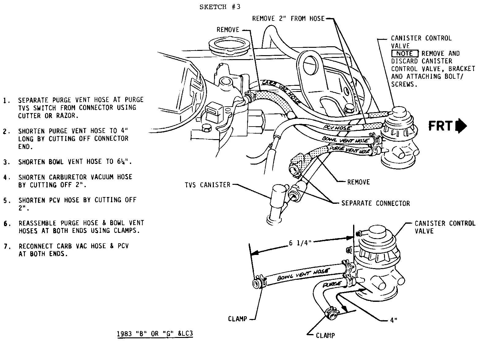
IV. 1983 "B" or "G" and LC3 (refer to Sketch #3)
1. Remove bracket from water outlet and from canister control valve (CCV). Discard bracket and two (2) retaining screws.
2. Reinstall water outlet bolt.
3. Separate purge vent hose at purge TVS switch from connector using cutter or razor.
4. Shorten purge vent hose to 4" long by cutting off connector end.
5. Shorten bowl vent hose to 6 1/4".
6. Shorten carburetor vacuum hose by cutting off 2".
7. Shorten PCV hose by cutting off 2".
8. Reassemble purge hose and bowl vent hoses at both ends using clamps.
9. Reconnect carburetor vacuum hose and PCV at both ends.
Use applicable labor operation.
General Motors bulletins are intended for use by professional technicians, not a "do-it-yourselfer". They are written to inform those technicians of conditions that may occur on some vehicles, or to provide information that could assist in the proper service of a vehicle. Properly trained technicians have the equipment, tools, safety instructions and know-how to do a job properly and safely. If a condition is described, do not assume that the bulletin applies to your vehicle, or that your vehicle will have that condition. See a General Motors dealer servicing your brand of General Motors vehicle for information on whether your vehicle may benefit from the information.
