SERVICE MANUAL UPDATE SEC. 8A HATCH & REAR LID ASSY.

Subject: HATCH PULL-DOWN/RELEASE UNIT AND CONVERTIBLE REAR LID LATCH ASSEMBLY
Models Affected: 1991 CAMARO
PLEASE REFERENCE THIS BULLETIN IN THE 1991 SERVICE MANUALS UNDER SECTION 8A AND 10.
This bulletin is issued to inform dealers that Interim 1991 Chevrolet Camaro models (VIN Breakpoint 173202) will be receiving a new hatch pulldown/release unit. The convertible models will be equipped with a new rear compartment lid latch assembly.
This bulletin provides the necessary Service Manual Information pertaining to the diagnostic procedures, repair procedures and part numbers for components.
This bulletin also provides Labor operation Codes, Operation Description and Labor Times that are applicable to each replacement part.
IMPORTANT: Use grease, GM part number 12345718 only when replacing parts. Failure to do so will result in shortened part life.
SECTION 8A
ELECTRICAL DIAGNOSIS CAMARO
Cell Index 135 Hatch Pull-Down Release
INDEX Page Hatch Pull-Down Release ........... 135-0
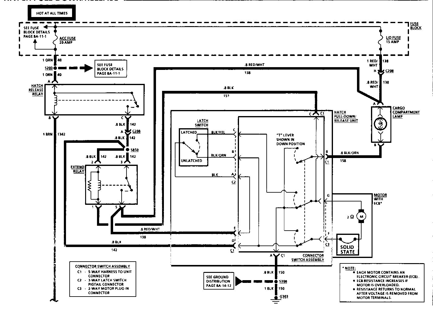
COMPONENT LOCATION PAGE - FIGURE -------------------- ------------------------- -------------- Cargo Compartment Lamp.......Center of rear cargo compartment panel Daytime Running Lights.......Behind LH Side of L/P .................201-12-A (DRL) Module Extend Relay.................Taped back to Body Rear Harness, near breakout to Hatch Pull-Down/Release Unit Fuse Block...................Behind LH side of I/P .................201-12-B Gear Selector Switch.........In console at Gear Selector............201-18-C Hatch Pull-Down/.............Center of rear end panel, in cargo compartment Release Unit Hatch Release Relay..........Behind RH side of I/P..................201-16-D Hatch Release Switch.........Center of I/P Parking Brake Switch.........In console, at base of Parking Brake Lever...................201-14-E Starter Solenoid.............Lower RH side of Engine................201-1-C (VIN E) Starter Solenoid.............Lower RH side of Engine................201-7-B (VIN F) (VIN 8) Starter Solenoid.............Lower RH side of Engine................201-4-A (VIN T) C100 (42 cavities)...........LH front of I/P........................201-10-A C204 (I cavity)..............Behind RH side of I/P ..............201-16-D C208 (8 cavities)............LH rear corner of cargo compartment....201-19-C G303.........................Center of rear end panel, in cargo compartment.................201-19-B S104.........................I/P Harness, behind LH side of I/P.....201-13-A S203.........................I/P Harness, behind LH side of I/P.....201-12-A S224.........................I/P Harness, behind LH side of I/P.....201-12-A S228.........................I/P Harness, behind LH side of I/P.....201-12-A S308.........................Body Rear Harness, near LH Turn Lamp...201-19-A S850.........................In Body Rear Harness, approx 7 cm left of breakout to Hatch Pull-Down Release Unit
TROUBLESHOOTING HINTS
(Perform before beginning System Diagnosis)
1. If both the ACC and LID Fuses are open, check for shorted motor windings or for short to ground in circuits capable of receiving B + from either fuse.
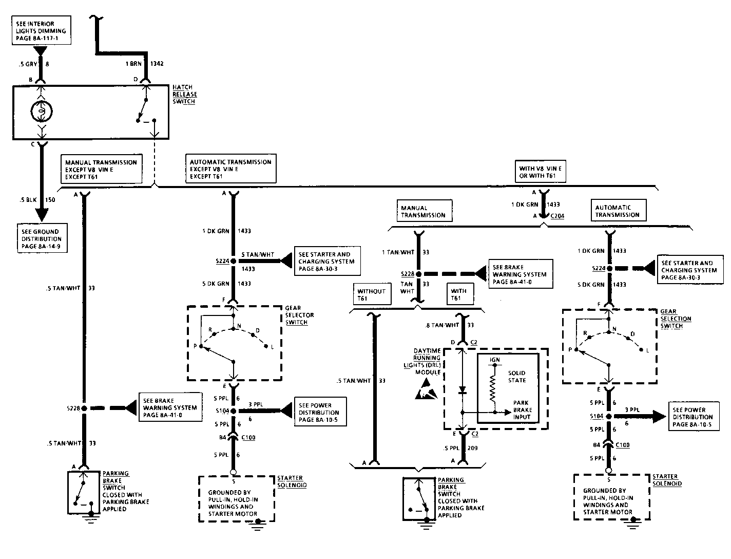
2. Check for proper operation of the Brake Warning System (Manual Transmission) or the Starting System (Automatic Transmission). Repair any faults in these systems before attempting to diagnose the Hatch Pull-Down/Release System.
SYMPTOM TABLE
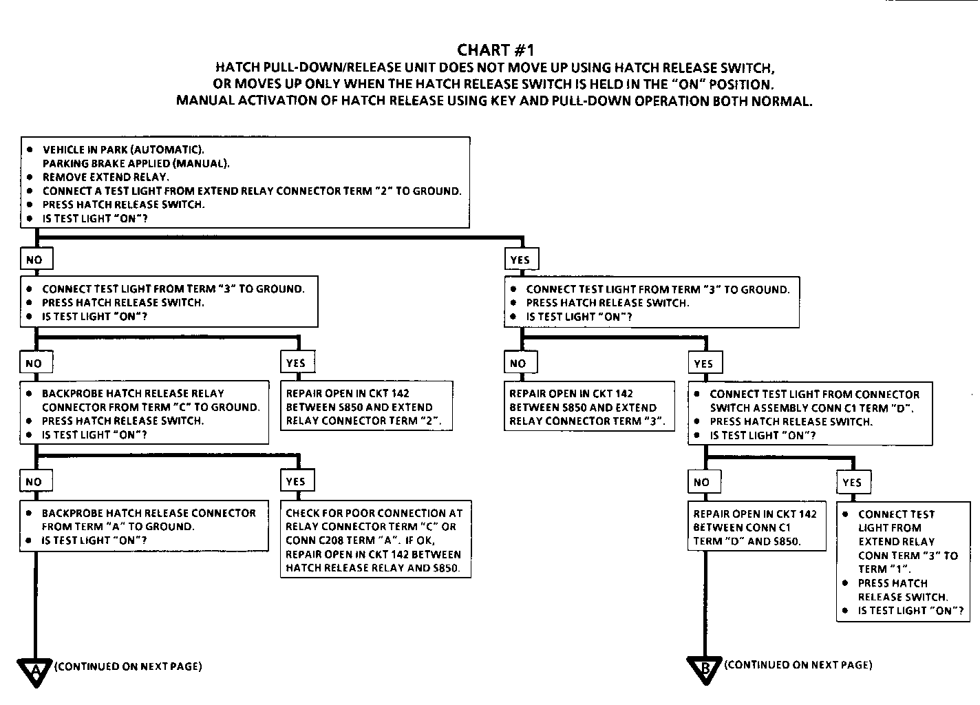
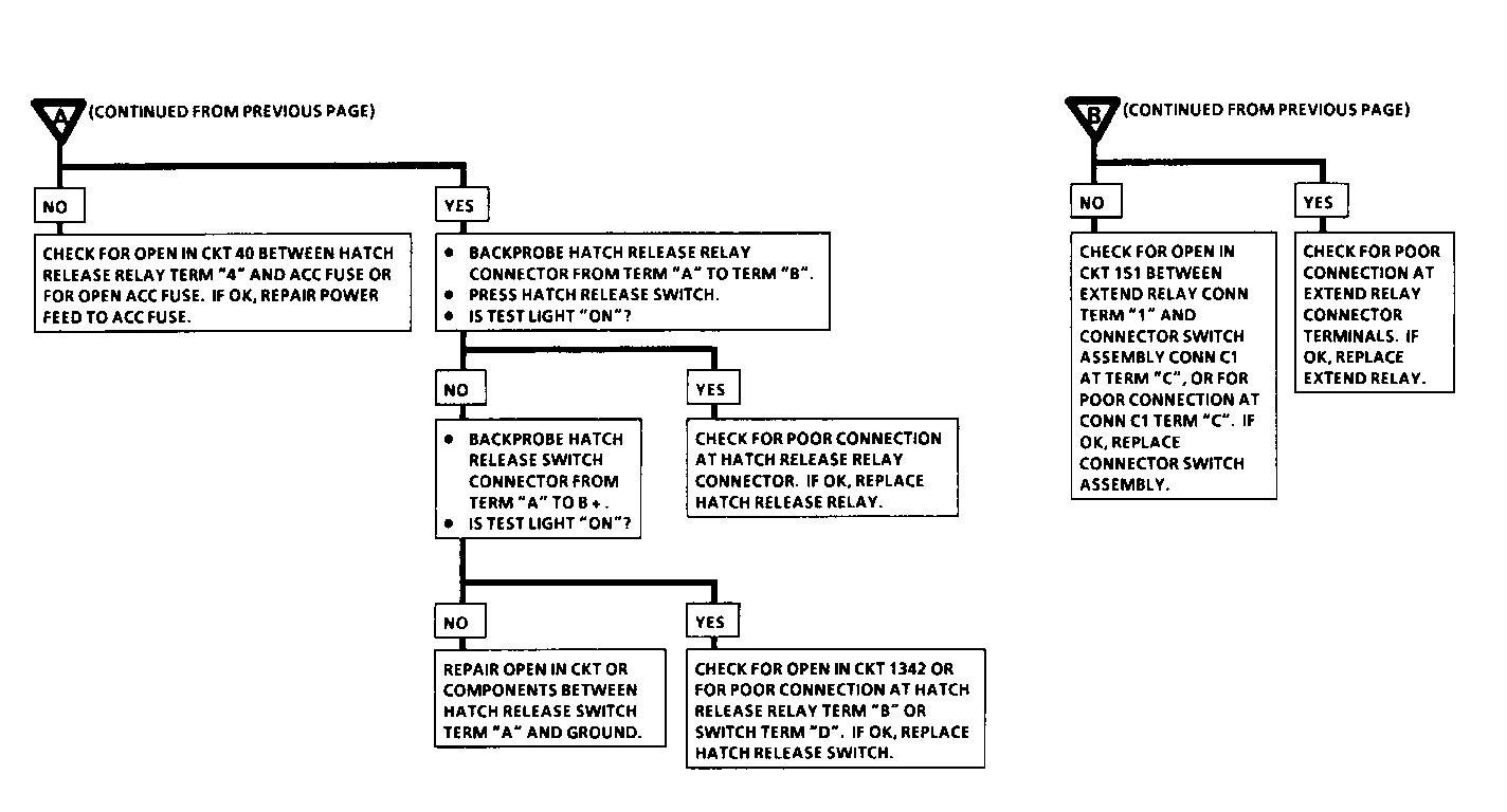
SYMPTOM PROCEDURE PAGE NUMBER ------------------------------------ ----------- ------------ Hatch Pull-Down/Release Unit does not move up using Hatch Release Switch, or moves up only when the Hatch Release Switch is held in the Chart #1 8A-135-4 "ON' position. Manual activation of Hatch Release using key and Pull-Down operation both normal.
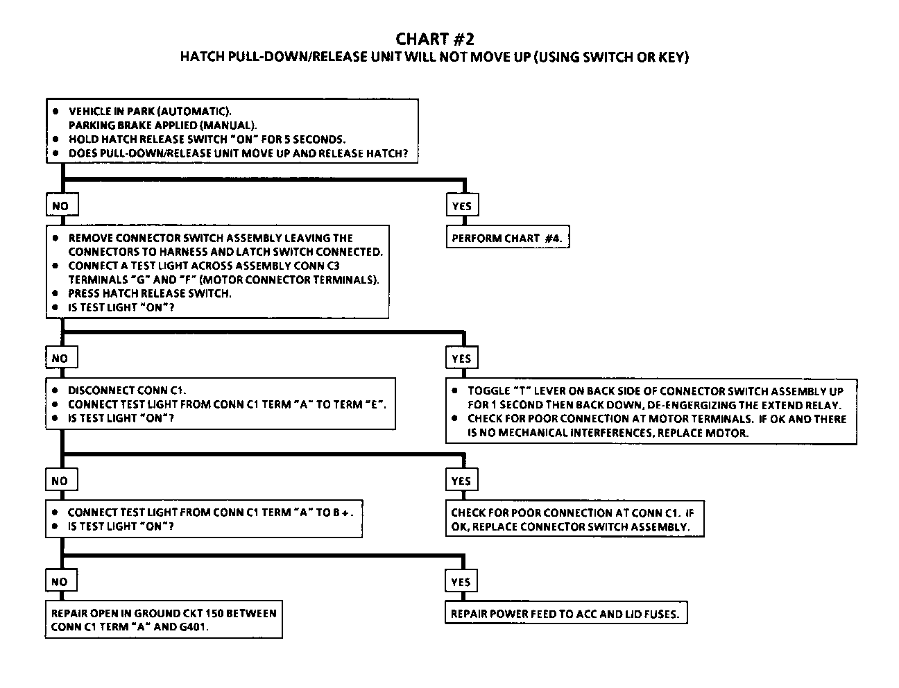
Hatch Pull-Down/Release Unit will Chart #2 8A-135-6 not move up (using switch or key).
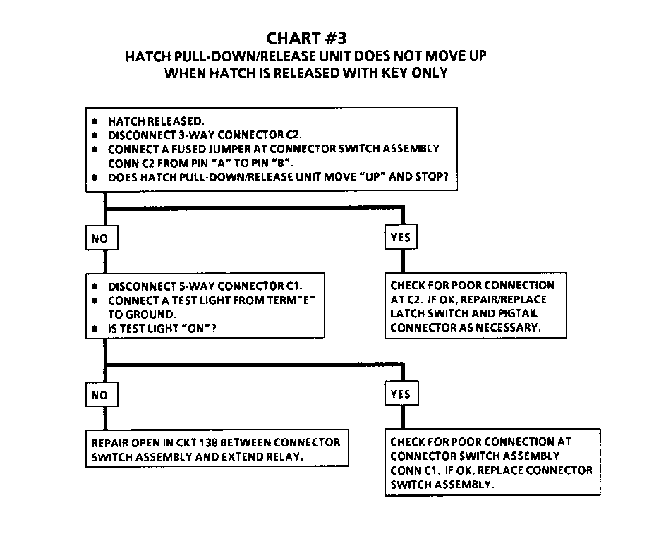
Hatch Pull-Down/Release Unit will Chart #3 8A-135-7 not move up when Hatch is released with key only.
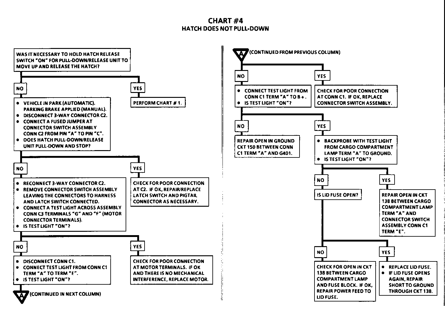
Hatch does not Pull-Down. Chart #4 8A-135-8
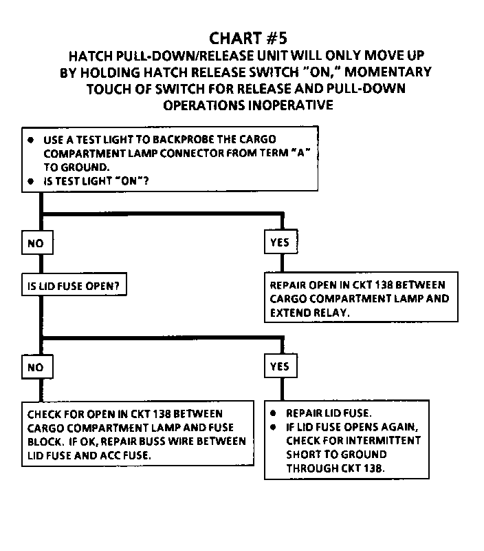
Hatch Pull-Down/Release Unit will Chart #5 8A-135-9 only move up by holding Hatch Release Switch "ON," momentary touch of switch for release and Pull-Down operation inoperative.
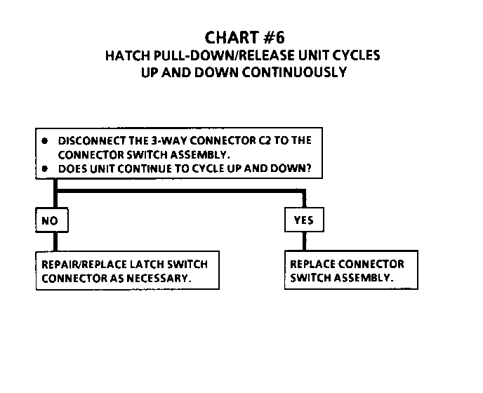
Hatch Pull-Down/Release Unit cycles Chart #6 8A-135-9 up and down continuously.
Hatch does not release with unit all Check for mechanical interference. the way up or when key is used. Refer to BODY REAR END (SEC 10-8).
CIRCUIT OPERATION
The Hatch Pull-Down Release Unit has three modes of operation:
EXTEND AND RELEASE
When the Hatch Release Switch is pressed momentarily, the Unit extends and consequently releases the Hatch.
RELEASE AND EXTEND
Whenever the Hatch is released manually with a key, the unit extends to be ready for Pull-Down operation.
PULL-DOWN
When the Hatch is pushed down manually into the Latch, the Hatch is pulled down.
1. EXTEND AND RELEASE OPERATION --------------------------------- When the Hatch Release Switch is pressed, it supplies a ground path to the Hatch Release Relay or CKT 1342. With the Release Relay energized, battery voltage is applied from the ACC Fuse, and CKT 40 to CKT 142. Battery voltage is always applied to CKT 138 from the LID Fuse. The Extend Relay is initially energized from CKT 142 and the Release Relay, once energized, the always present battery voltage at terminal "5" of the Extend Relay will continue to energize the Extend Relay. With voltage applied to the Connector Switch Assembly at connector C1 terminal "D" and ground supplied to terminal "A", the motor will be energized. With the Motor energized, positive at terminal "F" and negative at terminal "G", the Hatch Pull-Down/Release Unit will extend upward. While extending upward, a deflector on the back side of the Unit mechanically releases the Latch, allowing the Hatch to raise and the Latch Switch to move to the "UNLATCHED" position. The unit stops when the "T" Lever on the Connector Switch Assembly is mechanically toggled. The ground CKT 151 to the Extend Relay is opened and the Extend Relay de-energizes.
2. RELEASE AND EXTEND OPERATION ---------------------------------- When the Hatch is released manually with a key, the Hatch raises and the Latch Switch toggles to the "UNLATCHED" position. When this happens, battery voltage present at the Connector Switch Assembly connector C1 terminal "E" from CKT 138, is applied both to the Motor at terminal "F" and to CKT 142 at connector C1 terminal "D". With the Extend Relay and the Motor now energized, the system will operate the same as if the Hatch Release Switch had been pressed. Refer to #1 operation.
3. PULL-DOWN OPERATION ------------------------- When the Hatch is pushed down manually into the Latch, the Latch Switch is moved to the "LATCHED" position. Battery voltage from the LID Fuse and CKT 138 is always applied to the Connector Switch Assembly at connector C1 terminal "E". With the Latch Switch in the "LATCHED" position and the "T" Lever in the "UP" position, battery voltage is applied to the Motor at terminal "G" from the Latch Switch BLK/YEL wire to connector C2 terminal "C". Ground is supplied to the Motor at terminal "F" from terminal "A" of connector C1. With battery voltage to the Motor terminal "G", the Hatch Pull-Down/Release Unit will pull down and stop only when the "T" Lever is mechanically toggled to the "DOWN" position.
If the Hatch is pushed down before the Hatch Pull-Down Unit has fully extended, the Extend Relay will hold power to the Motor until the extend operation has completed. This will allow for normal Pull-Down operation to occur immediately after.
SECTION 10-7
NOTICE: When fasteners are removed, always reinstall them at the same location from which they were removed. If a fastener needs to be replaced, use the correct part number fastener for that application. If the correct part number fastener is not available, a fastener of equal size and strength (or stronger) may be used. Fasteners that are not reused, and those requiring thread locking compound will be called out. The correct torque value must be used when installing fasteners that require it. If the above conditions are not followed, parts or system damage could result.
CONTENTS
On-Vehicle Service.......................... 10-7-1 Hatch Pull-Down/Release Unit............. 10-7-1 Lock Cable............................. 10-7-1 Connector Switch Assembly.............. 10-7-1 Motor.................................. 10-7-1 Washer................................. 10-7-3 Gearnut................................ 10-7-3 Gearnut Bearing........................ 10-7-3 Latch Assembly ........................ 10-7-3 Shoes.................................. 10-7-3 Latch Switch........................... 10-7-4 Convertible Rear Compartment Lid Latch Assembly......................... 10-7-4 Lock Cable............................. 10-7-5 Lid Latch Switch....................... 10-7-5 Fastener Torque Specifications............ 10-7-5 Service Parts Information................... 10-7-5 Labor Operations............................ 10-7-6
ON-VEHICLE SERVICE
HATCH PULL-DOWN/RELEASE UNIT ----------------------------- For removal procedures, refer to "Compartment Lift Window Pull-Down Unit" in BODY REAR END (SEC. 10-7) in the service manual.
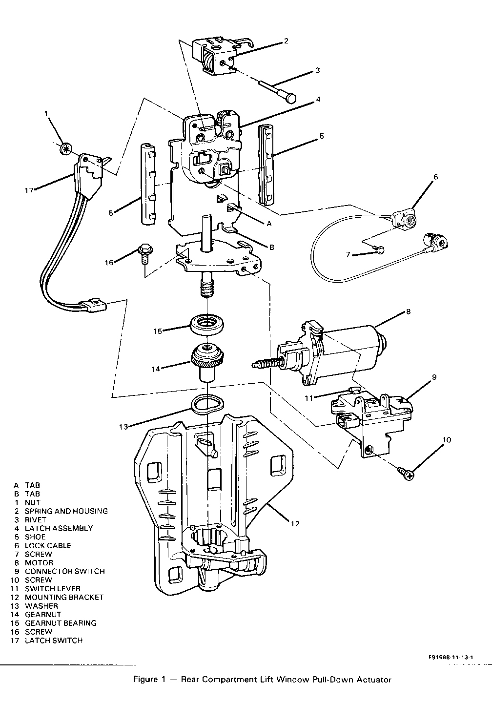
Lock Cable Figure 1
[< >] Remove or Disconnect
1. Pull-down/release unit. Refer to "Compartment Lift Window Pull-Down Unit" in BODY REAR END (SEC. 10-7) in the service manual.
2. Screw (7).
3. Lock cable (6) from latch assembly (4).
[> <] Install or Connect
1. Lock cable (6) to latch assembly (4).
2. Screw (7).
3. Pull-down/release unit. Refer to "Compartment Lift Window Pull-Down Unit" in BODY REAR END (SEC. 10-7) in the service manual.
Connector Switch Assembly Figure 1
[< >] Remove or Disconnect
1. Rear end trim panel. Refer to BODY REAR END (SEC. 10-7) in the service manual. 2. Electrical connector at connector switch (9). 3. Screw (10). 4. Connector switch (9).
[> <] Install or Connect [!] Important Before reinstalling the switch, verify that the switch lever (11) is positioned between tabs (A) and (B).
1. Connector switch (9). 2. Screw (10). 3. Electrical connector at connector switch (9). 4. Rear end trim panel. Refer to BODY REAR END (SEC. 10-7) in the service manual.
Motor Figure 1
[< >] Remove or Disconnect
1. Connector switch. Refer to "Connector Switch Assembly" in this service bulletin. 2. Screws (16). Slide the latch assembly (4) upward just enough to disengage the gearnut (14) from the motor (8). 3. Motor (8).
[> <] Install or Connect When installing a new motor (8), coat the motor armature shaft with grease, GM part number 12345718.
1. Motor (8).
o Slide the latch assembly (4) downward to engage the gearnut (14) to the motor (8).
[!] Important Make sure that the washer (13) is attached to the gearnut (14) to ensure easy installation.
2. Screws (16). 3. Connector switch. Refer to "Connector Switch Assembly" in this service bulletin.
Washer Figure 1
[< >] Remove or Disconnect
1. Connector switch. Refer to "Connector Switch Assembly" in this service bulletin. 2. Screws (16). Slide the latch assembly (4) upward high enough to disengage the gearnut (14) from the motor (8). 3. Washer (13).
[> <] Install or Connect When installing a new washer (13), coat the washer with grease, GM part number 12345718.
1. Washer (13) to gearnut (14). o Make sure that washer (13) stays attached to gearnut (14) to ensure easy installation.
o Slide the latch assembly (4) downward to engage the gearnut (14) to the motor (8).
[!] Important Make sure that the gearnut bearing (15) is seated on the gearnut (14) before installing screws (16).
2. Screws (16). 3. Connector switch. Refer to "Connector Switch Assembly" in this service bulletin.
Gearnut Figure 1
[< >] Remove or Disconnect
1. Washer. Refer to "Washer" in this service bulle- tin. 2. Gearnut (14) from the latch assembly (4).
[> <] Install or Connect When installing a new gearnut (14), coat it with grease, GM part number 12345718.
1. Gearnut (14) to latch assembly (4).
[!] Important Make sure that the gearnut bearing (15) is seated on the gearnut (14).
2. Washer. Refer to "Washer" in this service bulletin.
Gearnut Bearing Figure 1
[< >] Remove or Disconnect
1. Gearnut. Refer to "Gearnut" in this service bulletin. 2. Gearnut bearing (15).
[> <] Install or Connect When installing a new gearnut (14), coat the gearnut with grease, GM part number 12345718.
1. Gearnut bearing (15).
[!] Important When installing the gearnut bearing (15) make sure the flat surface of the gearnut bearing (15) is facing up.
2. Gearnut. Refer to "Gearnut" in this service bulle- tin.
Latch Assembly Figure 1
Remove or Disconnect
1. Gearnut bearing. Refer to "Gearnut Bearing" in this service bulletin. Slide the latch assembly (4) upward and separate it from the mounting bracket (12). 2. Shoes (5) from the latch assembly (4). 3. Rivet (3) and nut (1). 4. Spring and housing (2). 5. Latch switch (17). 6. Screw (7). 7. Lock cable (6).
Install or Connect
When installing a new latch assembly (4), coat the shoes (5) with grease, GM part number 12345718.
1. Lock cable (6) to latch assembly (4). 2. Screw (7). 3. Latch switch (17). 4. Spring and housing (2). 5. Rivet (3) and nut (1). 6. Shoes (5) to the latch assembly (4). Slide the latch assembly (4) downward into the slots in mounting bracket (12). 7. Gearnut bearing. Refer to "Gearnut Bearing" in this service bulletin.
Shoes Figure 1
[< >] Remove or Disconnect
1. Connector switch. Refer to "Connector Switch Assembly" in this service bulletin. 2. Screws (16). Slide the latch assembly (4) upward and separate it from the mounting bracket (12). 3. Shoes (5).
[> <] Install or Connect
1. Shoes (5). o When installing new shoes (5), coat the shoes with grease, GM part number 12345718.
o Slide the latch assembly (4) downward into the slots in mounting bracket (12).
2. Screws (16). 3. Connector switch. Refer to "Connector Switch Assembly" in this service bulletin.
Latch Switch Figure 1
[< >] Remove or Disconnect
1. Connector switch. Refer to "Connector Switch Assembly" in this service bulletin. 2. Screws (16). Slide the latch assembly (4) upward and separate it from the mounting bracket (12). 3. Rivet (3) and nut (1). 4. Spring and housing (2). 5. Latch switch (17).
Install or Connect
1. Latch switch (17). 2. Spring and housing (2). 3. Rivet (3) and nut (1). o Slide the latch assembly (4) downward into the slots in mounting bracket (12). 4. Screws (16). 5. Connector switch. Refer to "Connector Switch Assembly" in this service bulletin.
CONVERTIBLE REAR COMPARTMENT LID
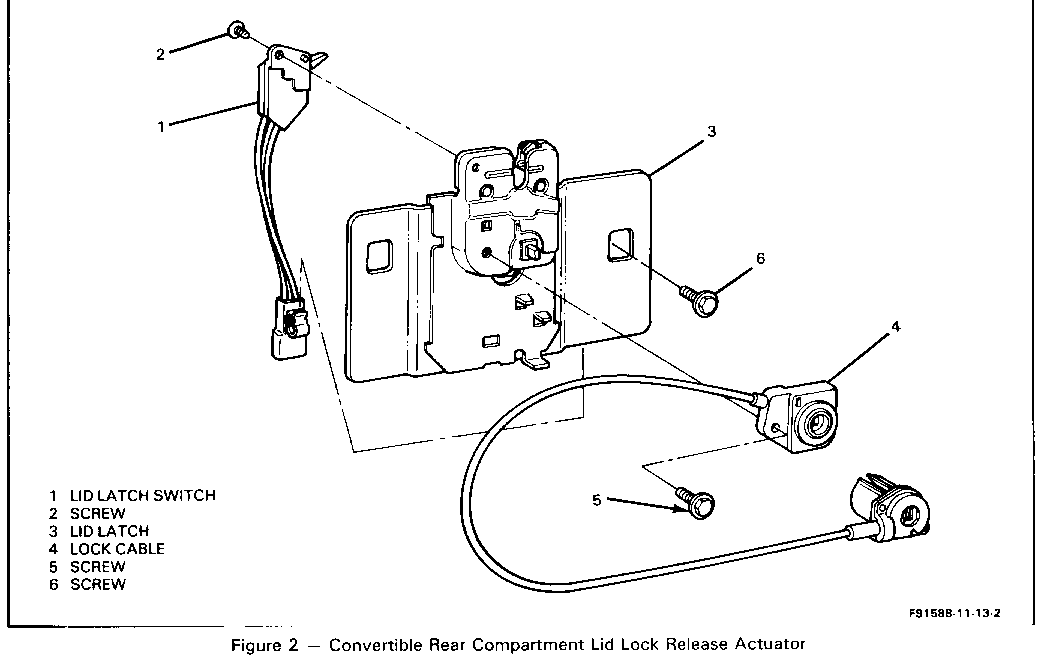
Latch Assembly Figure 2
Remove or Disconnect
1. Rear end trim panel. Refer to BODY REAR END (SEC. 10-7) in the service manual. 2. Electrical connector from the lid latch switch (1). 3. Screws (6). 4. Lid latch assembly lock cable connection from the lock cylinder. 5. Lid latch (3).
Install or Connect o Place the lid latch assembly near rear panel support.
1. Lock cable connection through opening in the support to the lock cylinder. 2. Lid latch (3) to the rear panel support. 3. Screws (6).
Adjust Lid latch assembly as necessary for proper lock striker engagement. o Tighten Screws (6) to 24 N-m (18 lb. ft.).
4. Electrical connector. 5. Rear end trim panel. Refer to BODY REAR END (SEC. 10-7) in the service manual.
Lock Cable Figure 2
Remove or Disconnect
1. Lid latch. Refer to "Convertible Rear Compartment Lid Latch Assembly" in this service bulletin. 2. Screw (5). 3. Lock cable (4).
Install or Connect
1. Lock cable (4). 2. Screw (5). 3. Lid latch. Refer to "Convertible Rear Compartment Lid Latch Assembly" in this service bulletin,
Lid Latch Switch Figure 2
Remove or Disconnect
1. Lid latch. Refer to "Convertible Rear Compartment Lid Latch Assembly" in this service bulletin. 2. Screw (2). 3. Lid latch switch (1).
Install or Connect
1. Lid latch switch (1). 2. Screw (2). 3. Lid latch. Refer to "Convertible Rear Compartment Lid Latch Assembly" in this service bulletin.
SPECIFICATIONS
FASTENER TORQUE SPECIFICATIONS
Lid Latch Switch Mounting Screw.......................... 24 N-m (18 lb. ft.)
SERVICE PARTS INFORMATION
PART NAME SERVICE PARTS CATALOG SERVICE PARTS NUMBER REFERENCE NAME CATALOG GROUP
COUPE Hatch Pull-Down/ Release Unit..............ACTUATOR, R/COMPT L/WDO PULL-DN ...... 12.243 (A90) 16603989 (A90) 16603988 Lock Cable ............... ACTUATOR, C/LIFT REM REL .............12.242 16607734
Motor..................... MOTOR, C/LID PULL-DOWN ..............12.243 22086479
Washer.................... WASHER, R/COMPT LID PULL-DN ACTR ..... 12.243 20160594
Gearnut .................. GEARNUT, RR COMPT LID PULL-DN ........12.243 20160587
Gearnut Bearing............BEARING, RR COMPT LID PULL-DN MOT ....12.243 20160588
Latch Assembly............LOCK, R/COMPT L/WDO....................12.243 16604296
Shoe ..................... SHOE, COMPT L/PULL-DOWN UNIT .........12.243 16604270
Connector Switch Assembly ...... SWITCH, C/LIFT WDO PULL-DOWN MTR.....12.966 16604245
Latch Switch ............. SWITCH,COMPT L/WDO PULL-DN MTR UNIT....12.243 16622774
Rivet .................... RIVET..................................12.966 16605493
Nut ...................... RETAINER, PUSH-ON .................... 8.921 17058193
Grease ....................LUBRICANT, SPECIAL ................... 8.800. 12345718
CONVERTIBLE
Lid Latch Assembly ..... LATCH ASM, R/COMPT LID ................ 12.243 16623737
Lid Latch Switch ....... SWITCH, C/LID LAT ..................... 12.243 16622774
LABOR OPERATIONS
LABOR TIMES LABOR CODE OPERATION DESCRIPTION (HOURS) ----------- -------------------------------------- ----------- R4040 Actuator, Rear Compartment Lift Window .3 Pull-Down - Replace R4055 Motor, Rear Compartment Lid Pull-Down .4 - Replace R4030 Washer, Gearnut, and or Bearing, Rear .4 Compartment Lid Pull-Down Motor - Replace B5500 Lock, Rear Compartment Lift Window .5 (Sedan) - Replace B5500 Lock, Rear Compartment Lift Window .3 (Convertible) - Replace R4035 Shoe, Rear Compartment Lid Pull-Down .4 Unit - Replace R4050 Switch, Rear Compartment Lift Window .3 Pull-Down Motor - Replace R4045 Switch, Rear Compartment Lift Window .5 Pull-Down Motor Unit - Replace N2386 Switch, Rear Compartment Lid Latch .3 (Convertible) - Replace R4020 Actuator, Compartment Lift Remote .4 Release - Replace
General Motors bulletins are intended for use by professional technicians, not a "do-it-yourselfer". They are written to inform those technicians of conditions that may occur on some vehicles, or to provide information that could assist in the proper service of a vehicle. Properly trained technicians have the equipment, tools, safety instructions and know-how to do a job properly and safely. If a condition is described, do not assume that the bulletin applies to your vehicle, or that your vehicle will have that condition. See a General Motors dealer servicing your brand of General Motors vehicle for information on whether your vehicle may benefit from the information.
