SERVICE MANUAL UPDATE-SEC.6E2 ENHANCED EGR CIRCUIT DIAG.

VEHICLES AFFECTED: 1987-91 "B/D/F/G" 4.3L/5.0L/5.7L (VIN E,Z,7)
This information replaces the diagnostic charts and test descriptions found in the "Driveability and Emissions" Section 6E2-A (Code 32) and Section 6E2-C7 portions of the 1987-91 5.0L L03 (VIN E), 5.7L L05 (VIN 7), and 4.3L (VIN Z) "B", "D", "F", and "G" service manuals. (See table below.)
CARLINF VIN ENGINE YEAR
B Z 4.3L LB4 1987-90 B E 5.0L L03 1989-91 B 7 5.7L L05 1989-91
D 7 5.7L L05 1990
F E 5.0L L03 1988-91
G z 4.3L LB4 1987-88
For further information on code setting criteria and EGR operation, refer to the existing service manual sections that are listed above.
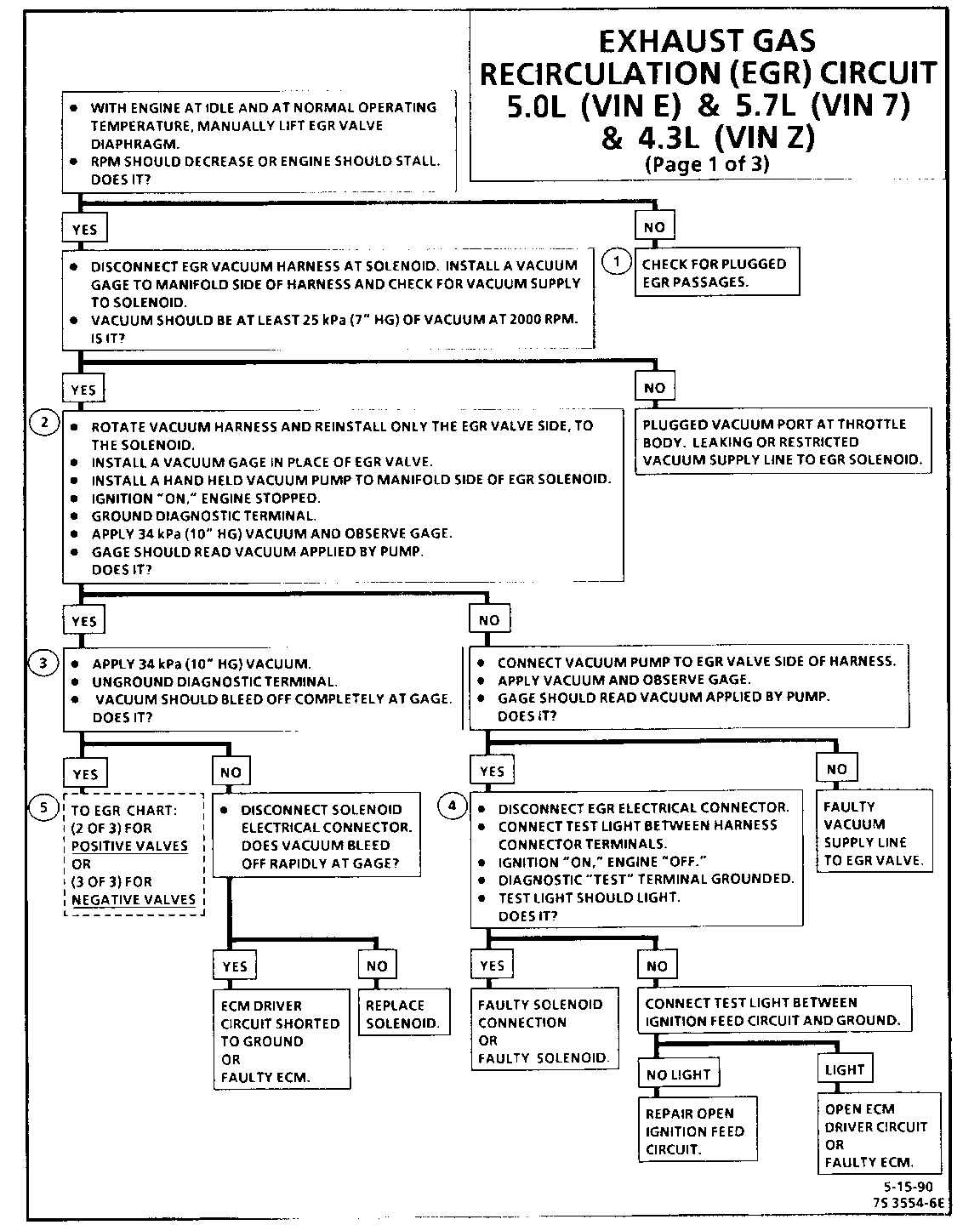
EXHAUST GAS RECIRCULATION (EGR) CIRCUIT 5.0L (VIN E) & 5.7L (VIN 7) & 4.3L (VIN Z) (Page 1 of 3)
Circuit Description:
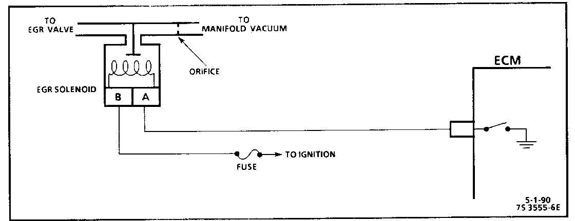
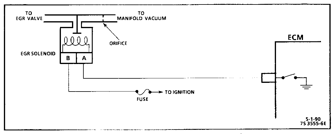
The Exhaust Gas Recirculation (EGR) system is controlled by the ECM. The ECM controls the vacuum being supplied to the valve by energizing and de-energizing a solenoid.
The ECM uses information from various engine sensors to determine when EGR is necessary. Once the ECM has requested EGR by grounding the solenoid circuit, the ECM will monitor engine operating conditions to determine if exhaust gas flow has entered the intake manifold. When the ECM tests for EGR operation and no change in engine operating conditions is indicated, a Code 32 will set.
Test Description: Numbers below refer to circled numbers on the diagnostic chart.
1. Intake Passage: Shut "OFF" engine and remove the EGR valve from the manifold. Plug the exhaust side hole with a suitable stopper. Leaving the intake side hole open, attempt to start the engine. If the engine runs at a high idle (up to 3000 rpm is possible) or starts and stalls, the EGR intake passage is not restricted. If the engine starts and idles normally, the EGR intake passage is restricted.
Exhaust Passage: With EGR valve still removed, plug the intake side hole with a suitable stopper. With the exhaust side hole open, check for the presence of exhaust gas. If no exhaust gas is present, the EGR exhaust side passage is restricted.
2. By grounding the diagnostic "test" terminal, the EGR solenoid should be energized and allow vacuum to be applied to the gage. The vacuum at the gage may or may not slowlv bleed off. It is important that the gage is able to read the amount of vacuum being applied.
3. When the diagnostic "test" terminal is ungrounded, the vacuum gage should bleed off completely through a vent in the solenoid. The vacuum pump gage may or may not bleed off but this does not indicate a problem.
4. This test will determine if the electrical control part of the system is at fault or if the connector or solenoid is at fault.
5. EGR valves used with this engine are stamped on the top side of the valve with: (P) for Positive backpressure valves or, (N) for Negative backpressure valves. Refer to "EGR Valve Identification" in Section "6E2-C7" for more information.
Diagnostic Aids:
Vacuum lines should be thoroughly checked for proper routing. Refer to "Vehicle Emission Control Information" label.
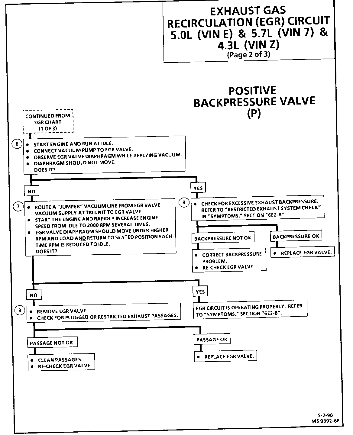
EXHAUST GAS RECIRCULATION (EGR) CIRCUIT 5.0L (VIN E) & 5.7L (VIN 7) & 4.3L (VIN Z) (Page 2 of 3)
Circuit Description:
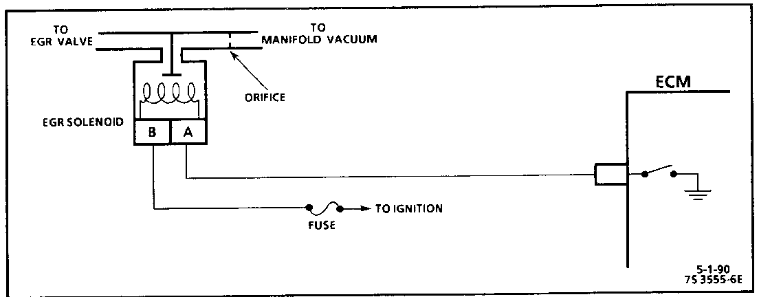
The Exhaust Gas Recirculation (EGR) system is controlled by the ECM. The ECM controls the vacuum being supplied to the valve by energizing and de-energizing a solenoid.
The ECM uses information from various engine sensors to determine when EGR is necessary. Once the ECM has requested EGR by grounding the solenoid circuit, the ECM will monitor engine operating conditions to determine if exhaust gas flow has entered the intake manifold. When the ECM tests for EGR operation and no change in engine operating conditions is indicated, a Code 32 will set.
Test Description (continued): Numbers below refer to circled numbers on the diagnostic chart.
6. The remaining tests check the ability of the EGR valve to interact with the exhaust system. This system uses a positive backpressure EGR valve which will not hold vacuum until sufficient exhaust back pressure is at the base of the valve.
7. The EGR valve diaphragm should move when sufficient exhaust backpressure is present at the base of the valve and when vacuum is being supplied to the valve. Rapidly "snapping" the throttle from idle should provide sufficient exhaust backpressure to the base of the valve which will close an internal vacuum bleed. With the EGR valve's internal vacuum bleed closed, the "jumpered" vacuum supply can now lift the valve off its seat. The amount of valve pintle movement will be small. It is important that the valve pintle moves at the proper time.
8. Excessive exhaust backpressure from bent or restricted exhaust system components could provide enough backpressure at the base of the EGR valve to close the valve's internal bleed and allow undesired EGR valve operation at idle.
9. Plugged EGR exhaust passages can block exhaust backpressure from reaching the EGR valve. With no EGR exhaust backpressure at the base of the valve, the valve's internal bleed will remain open and prevent vacuum from operating the valve.
Diagnostic Aids:
Suction from shop exhaust hoses can alter backpressure and may effect the functional check of the EGR valve.
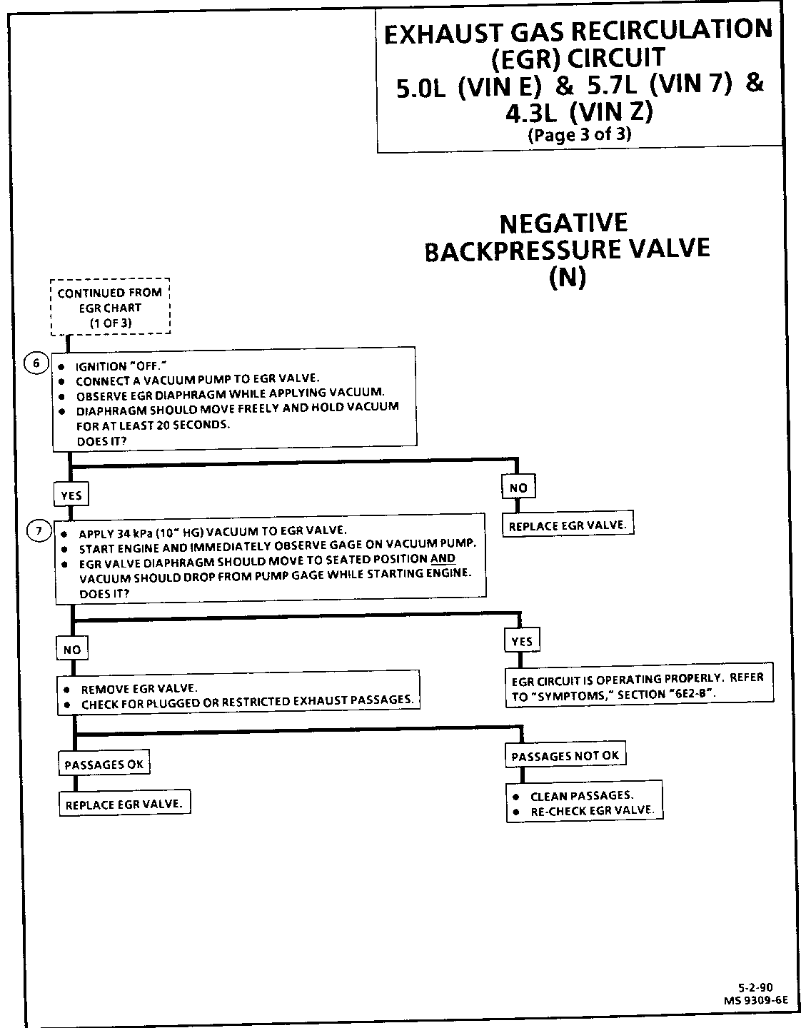
EXHAUST GAS RECIRCULATION (EGR) CIRCUIT 5.0L (VIN E) & 5.7L (VIN 7) & 4.3L (VIN Z) (Page 3 of 3)
Circuit Description:
The Exhaust Gas Recirculation (EGR) system is controlled by the ECM. The ECM controls the vacuum being supplied to the valve by energizing and de-energizing a solenoid.
The ECM uses information from various engine sensors to determine when EGR is necessary. Once the ECM has requested EGR by grounding the solenoid circuit, the ECM will monitor engine operating conditions to determine if exhaust gas flow has entered the intake manifold. When the ECM tests for EGR operation and no change in engine operating conditions is indicated, a Code 32 will set.
Test Description (continued): Numbers below refer to circled numbers on the diagnostic chart.
6. The remaining tests check the ability of the EGR valve to interact with the exhaust system. This system uses a negative backpressure EGR valve which should hold vacuum with engine "OFF. "
7. When engine is started, exhaust backpressure at the base of the EGR valve should open the valve's internal bleed and vent the applied vacuum allowing the valve to seat.
Diagnostic Aids:
Suction from shop exhaust hoses can alter backpressure and may effect the functional check of the EGR valve.
General Motors bulletins are intended for use by professional technicians, not a "do-it-yourselfer". They are written to inform those technicians of conditions that may occur on some vehicles, or to provide information that could assist in the proper service of a vehicle. Properly trained technicians have the equipment, tools, safety instructions and know-how to do a job properly and safely. If a condition is described, do not assume that the bulletin applies to your vehicle, or that your vehicle will have that condition. See a General Motors dealer servicing your brand of General Motors vehicle for information on whether your vehicle may benefit from the information.
