TWIN LIFT-OFF PANEL WATERLEAKS DIAGNOSIS/REPAIR PROCEDURE

Subject: TWIN LIFT-OFF PANEL WATERLEAKS
Model and Year: 1982-91 CAMARO
THIS BULLETIN CANCELS AND SUPERSEDES DEALER SERVICE BULLETIN NO. 86-129, DATED JULY 1986. THE MODEL YEARS HAVE BEEN UPDATED, PART NUMBER CHANGES AND INFORMATION ON COMPONENT IDENTIFICATION ADDED. ALL COPIES OF 86-129 SHOULD BE DISCARDED.
CONDITION: Some customers may comment about waterleaks on "F" style vehicles equipped with twin lift off hatch roof panels (CC1 option).
CAUSE: May include one or more of the following: - skips or voids in sealers on the roof weatherstrips - weatherstrip butt joints, improper contact - skips or voids in sealing of center "T" bar - improper door glass to weatherstrip contact
DIAGNOSIS: 1. Should be performed by watertesting the vehicle with the garnish moldings removed from the windshield pillar, lock pillar and lift off panel. 2. Should be performed by the technician doing the repairs. 3. Should refer to the chart included in this bulletin to aid in diagnosis.
CORRECTION: Repairs should be attempted only after the car has been properly watertested and diagnosed. It will not be necessary in all cases to replace weatherstrips.
The illustrations in this bulletin depict components on early style (1982-83) vehicles. The waterleak information remains correct regardless of year being repaired.
MATERIALS:
------------ FOR ADHESIVES/SEALANTS USE: 3M# 08011, AMERICAN/DOMINION SURE SEAL # BSSG-B OR GM # 12345097.
FOR CAULKING MATERIAL USE: 3M#08578 OR AMERICAN/DOMINION SURE SEAL BSC.
Materials other than those listed above may be comparable, but only the material specified is recommended.
NOTES: PART NUMBERS: 1982 TO 1987,1988 2ND Type and 1989 to 1991 Weatherstrip, lift off panel opening on body - 10198208 - 9 Weatherstrip, side roof rail on lift off glass - 10165500
PART NUMBERS: 1988 1ST Type Weatherstrip, lift off panel opening on body - 10064450-1 Weatherstrip, side roof rail on lift off glass - 10165500
NOTES: COMPONENT IDENTIFICATION
1. 1988 1st. design components have interlocking features on the opening weatherstrips and retainers. These components must not be intermixed with 1988 2nd. design and other years. The panel weatherstrip and retainers are common between various designs.
2. 1982 -1987, 1988 2nd. design and 1989-1991 are common in design.
3. The panel weatherstrip no longer attaches with screws to the panel at the butt joint locations, and must be glued into position.
4. The latest weatherstrips are silicone coated to reduce squeaking/ticking noises of glass to weatherstrips. If weatherstrip replacement is required, both (opening and panel) should be replaced as a set to obtain the best anti-squeak results and maintain appearance (gloss levels).
Parts are currently available from GMSPO.
Use published operations and time allowances.
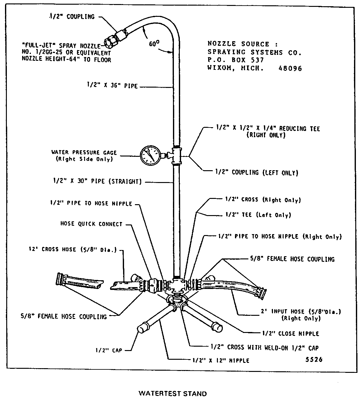
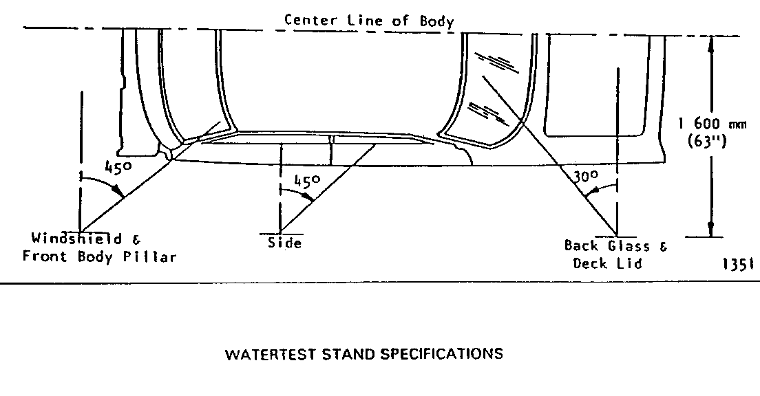
WATERTEST STAND SPECIFICATIONS (Figure 2)
Type of Nozzle - Full cone spray with 600 included angle - "Full Jet" Spray Nozzle No. 1/2 GG-25 or equivalent.
Nozzle Height - Approximately 1 600 mm (63") from floor
Volume of Flow - 14 liters (3.7 gallons) per minute
Pressure - 155 kPa (22 psi) measured at'-nozzle
Windshield and Front Body Pillar - approximately 30 degrees down, 45 degrees toward rear and aimed at corner of windshield.
Side - approximately 30 degrees down, 45 degrees toward rear and aimed at center of rear door or rear quarter.
Back Window and Rear Compartment Lid - approximately 30 degrees down, 30 degrees toward front and aimed approximately 600 mm (24") from corner of back window.
WATERLEAK DIAGNOSIS CHART
WATER ENTRY AT PROBABLE CAUSE(S) OF LEAK ILLUSTRATED ON
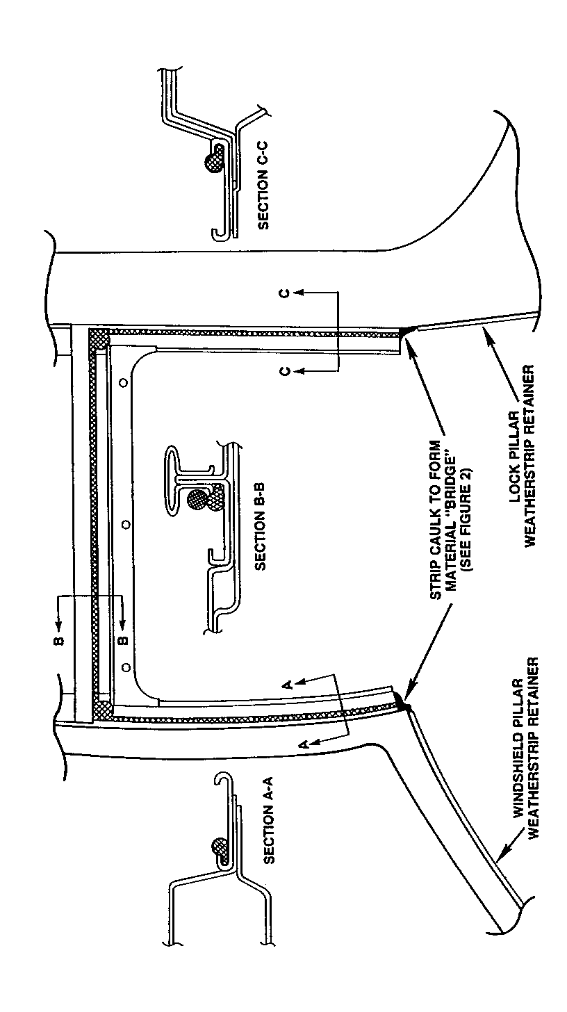
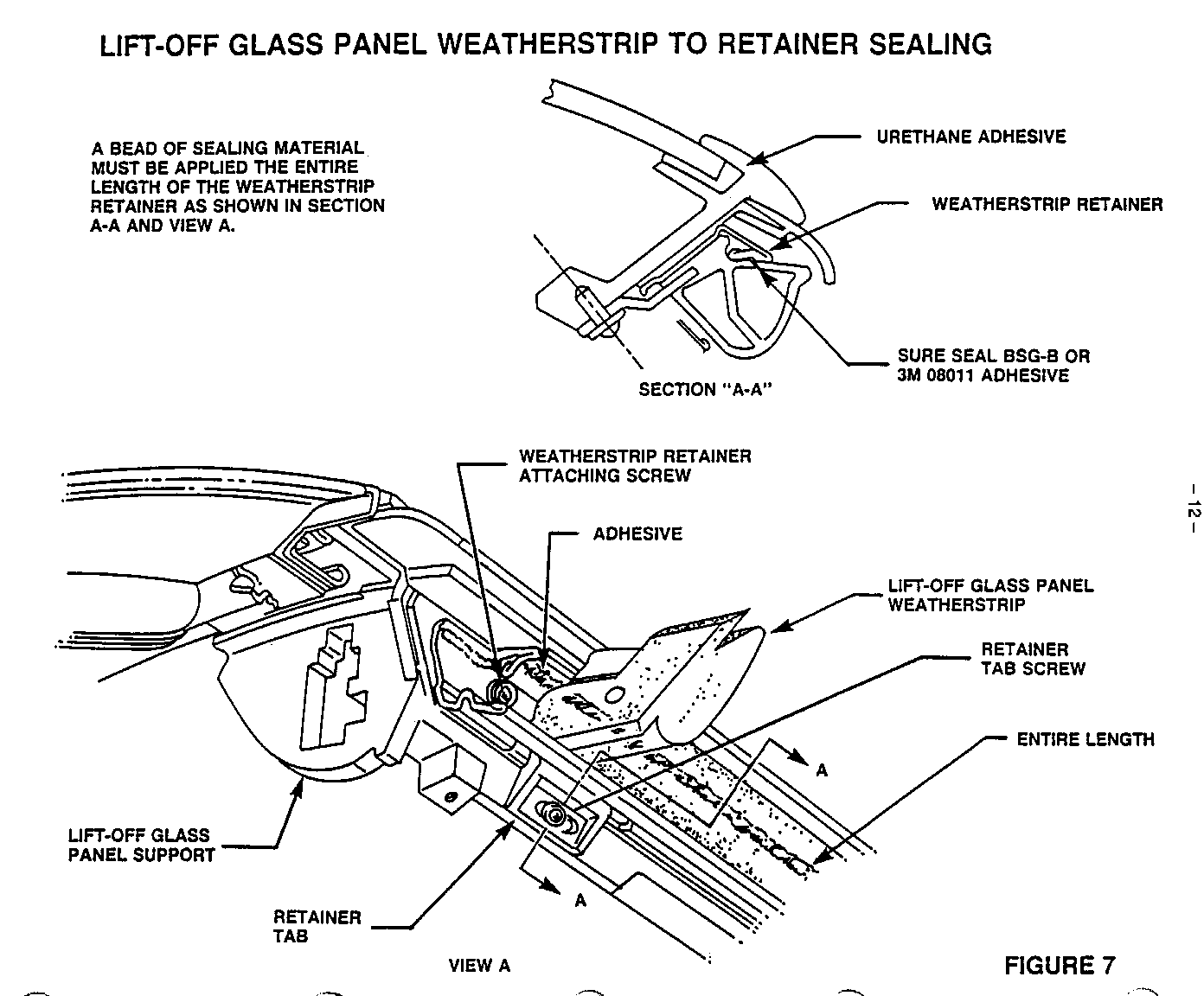
- Headliner - -Skips or voids in - Figure #1 between twin sealing of body lift-off roof seams underneath panels or at twin lift-off rear of roof. panel center upper finishing molding. ----------------------------------------------------------------------------- - Outboard corners - Skips or voids in - Figure #2 of weatherstrip the caulking or between roof bridge material sheet metal and between the weatherstrip. weatherstrip and roof sheet metal. ----------------------------------------------------------------------------- - Any area between - Skips or voids - Figure #3 roof portion of in weatherstrip weatherstrip and adhesive - Figure #4 retainers or at outboard ends of - Skips or voids - Figure #5 retainers. in Secondary Sealing ----------------------------------------------------------------------------- - Twin-lift-off panel - Skips, voids or - Figure #6 between outer plastic improperly sealed - Figure #7 support panel and the weatherstrip sealing strip, retainers, weatherstrip and/or weatherstrips or weatherstrip retainer. sealing strips. ----------------------------------------------------------------------------- - Twin lift-off panel - Skips or voids - Figure #7 between glass and in urethane adhesive outer plastic support panel. ----------------------------------------------------------------------------- - Door glass to - Misaligned, - Figure #8 misadjusted twin side weatherstrips lift-off panel (especially at the weatherstrip at butt Joint areas) butt joints. - Refer to Body portion of Service - Misaligned, Manual. misadjusted door glass. -----------------------------------------------------------------------------
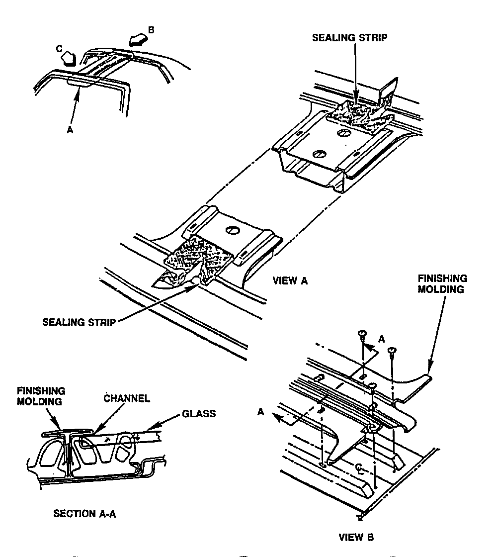
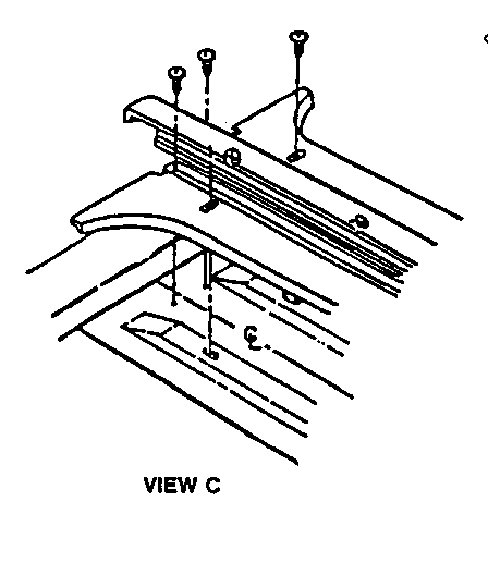
LIFT-OFF PANEL OPENING CENTER UPPER FINISH MOLDING SEALING AND INSTALLATION
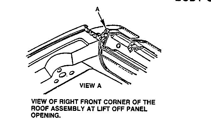
(Figure 3) 1. TO ELIMINATE WATER ENTRY AT THE HEADLINING AREA REAR OF THE LIFT OFF PANEL, RAISE SEALING STRIP AND APPLY SURE SEAL LSW OR 3M08531 ALONG FRONT AND REAR CUTOUT SEAMS
2. REINSTALL SEALING STRIPS (VIEW A) TO COVER THE FRONT AND REAR CUTOUT SEAMS.
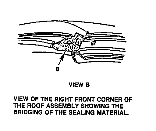
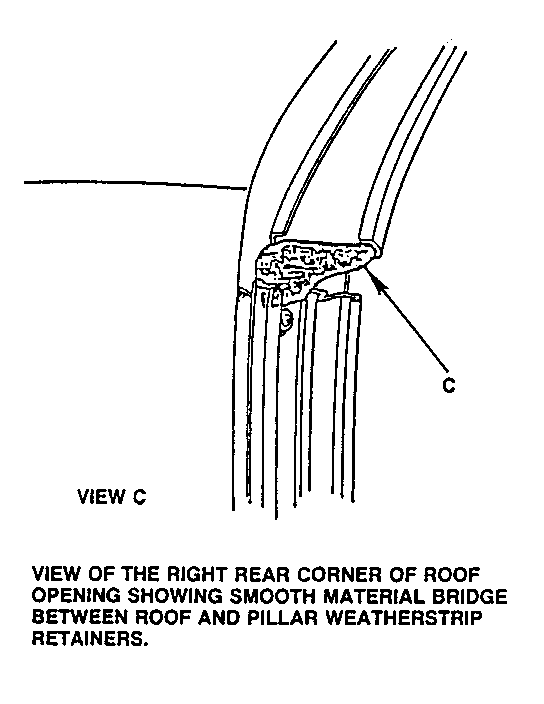
3. APPLY FINISHING MOLDING AS SHOWN IN VIEWS B AND C.
4. LIFT OFF PANEL CHANNEL (SECTION A-A) MUST BE PARALLEL WITH FINISHING MOLDING. IF CHANNEL IS NOT PARALLEL, WHEN OUTBOARD FRONT AND REAR CORNERS OF LIFT OFF PANEL ARE FLUSH AND IN-LINE WITH ROOF. THE MOUNTING HOLES IN FINISHING MOLDING MUST BE ENLARGED AND FINISHING MOLDING REALIGNED.
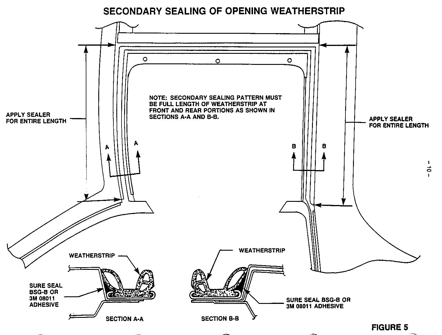
SEALING LOCATIONS AND PATTERNS FOR BODY OPENING WEATHERSTRIP. (Figure 5) ------------------------------------------------------------------------ APPLY A COAT OF 3M-08643 WINDOW WELD PRIMER AS A CORROSION PROTECTION IN AREAS OF PAINT DAMAGE DONE DURING CLEANUP OPERATIONS.
APPLY A SMOOTH CONTINUOUS 3/16" BEAD OF 3M08011 OR SURE SEAL BSG-B ADHESIVE (AS SHOWN ABOVE) AROUND TOTAL BODY OPENING. IN THE OUTBOARD LIP OF RETAINERS.
APPLY A QUARTER SIZED AMOUNT OF 3M 08011 OR SURE SEAL BSG-B ADHESIVE IN THE FRONT AND REAR INBOARD CORNERS OF THE ROOF RETAINER.
APPLY A SMOOTH CONTINUOUS 1/8" BEAD OF EM08011 OR SURE SEAL BSG-B ADHESIVE IN THE OUTBOARD LIP OF THE WINDSHIELD PILLAR AND LOCK PILLAR WEATHERSTRIP RETAINERS
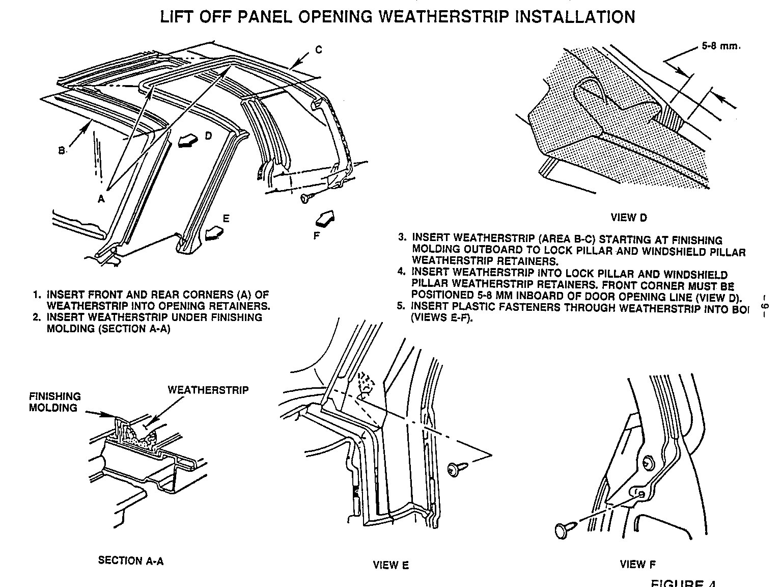
LIFT OFF PANEL OPENING WEATHERSTRIP INSTALLATION (Figure 6)
1. INSERT FRONT AND REAR CORNERS (A) OF WEATHERSTRIP INTO OPENING RETAINERS.
2. INSERT WEATHERSTRIP UNDER FINISHING MOLDING (SECTION A-A)
3. INSERT WEATHERSTRIP (AREA B-C) STARTING AT FINISHING MOLDING OUTBOARD TO LOCK PILLAR AND WINDSHIELD PILLAR WEATHERSTRIP RETAINERS.
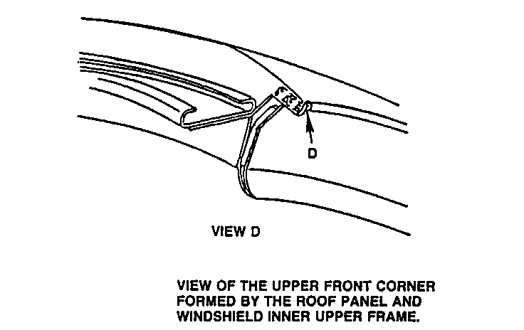
4. INSERT WEATHERSTRIP INTO LOCK PILLAR AND WINDSHIELD PILLAR WEATHERSTRIP RETAINERS. FRONT CORNER MUST BE POSITIONED 5-8 MM INBOARD OF DOOR OPENING LINE (VIEW D).
5. INSERT PLASTIC FASTENERS THROUGH WEATHERSTRIP INTO BOLT (VIEWS E-F).
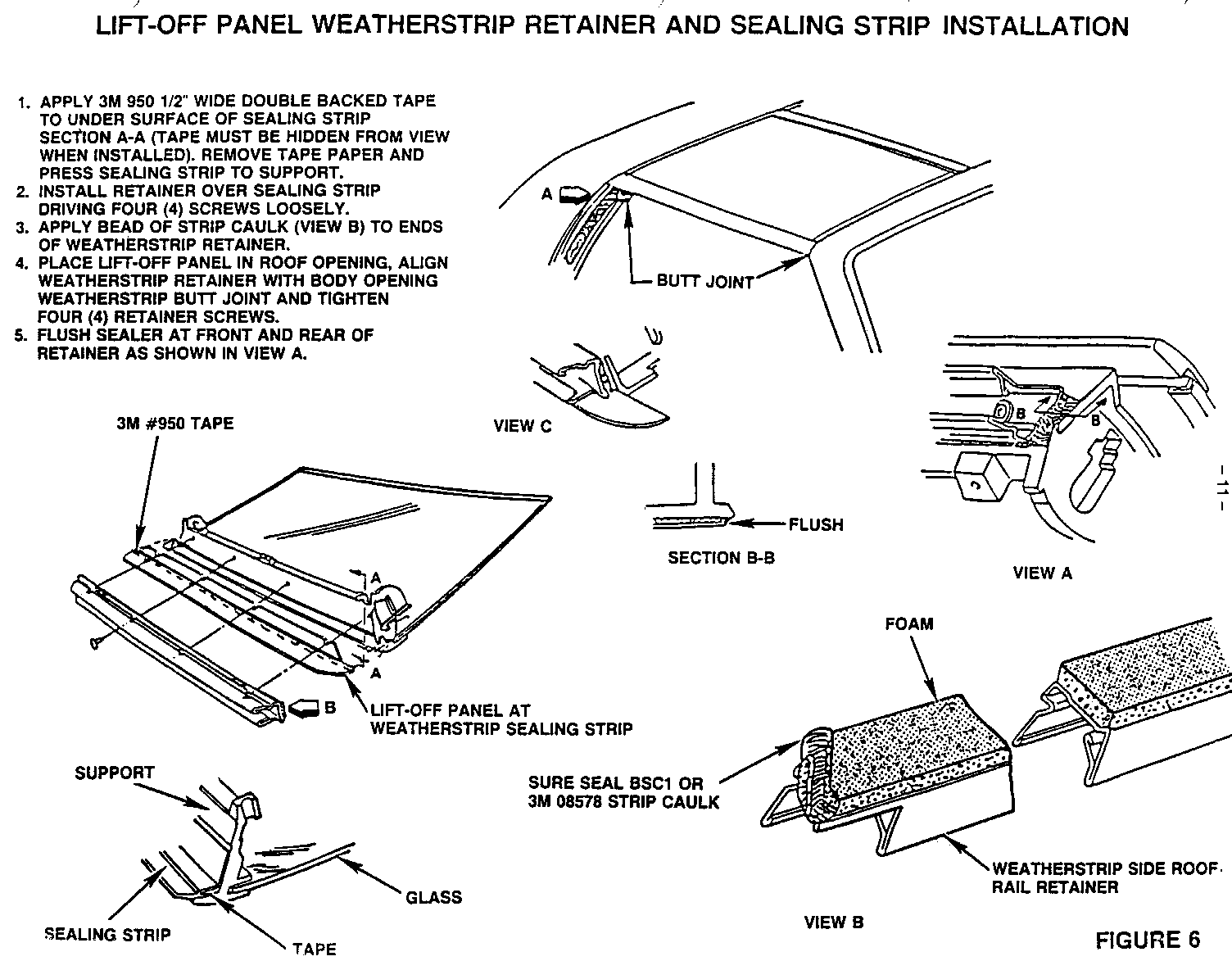
LIFT-OFF PANEL WEATHERSTRIP RETAINER AND SEALING STRIP INSTALLATION
(Figure 8) 1. APPLY 3M 950 1/2" WIDE DOUBLE BACKED TAPE TO UNDER SURFACE OF SEALING STRIP SECTION A-A (TAPE MUST BE HIDDEN FROM VIEW WHEN INSTALLED). REMOVE TAPE PAPER AND PRESS SEALING STRIP TO SUPPORT.
2. INSTALL RETAINER OVER SEALING STRIP DRIVING FOUR (4) SCREWS LOOSELY.
3. APPLY BEAD OF STRIP CAULK (VIEW B) TO ENDS OF WEATHERSTRIP RETAINER.
4. PLACE LIFT-OFF PANEL IN ROOF OPENING, ALIGN WEATHERSTRIP RETAINER WITH BODY OPENING WEATHERSTRIP BUTT JOINT AND TIGHTEN FOUR (4) RETAINER SCREWS.
5. FLUSH SEALER AT FRONT AND REAR OF RETAINER AS SHOWN IN VIEW A.
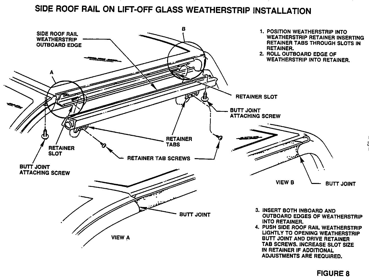
SIDE ROOF RAIL ON LIFT-OFF GLASS WEATHERSTRIP INSTALLATION (Figure 10)
1. POSITION WEATHERSTRIP INTO WEATHERSTRIP RETAINER INSERTING RETAINER TABS THROUGH SLOTS IN RETAINER.
2. ROLL OUTBOARD EDGE OF WEATHERSTRIP INTO RETAINER.
3. INSERT BOTH INBOARD AND OUTBOARD EDGES OF WEATHERSTRIP INTO RETAINER.
4. PUSH SIDE ROOF RAIL WEATHERSTRIP LIGHTLY TO OPENING WEATHERSTRIP BUTT JOINT AND DRIVE RETAINER TAB SCREWS. INCREASE SLOT SIZE IN RETAINER IF ADDITIONAL ADJUSTMENTS ARE REQUIRED.
General Motors bulletins are intended for use by professional technicians, not a "do-it-yourselfer". They are written to inform those technicians of conditions that may occur on some vehicles, or to provide information that could assist in the proper service of a vehicle. Properly trained technicians have the equipment, tools, safety instructions and know-how to do a job properly and safely. If a condition is described, do not assume that the bulletin applies to your vehicle, or that your vehicle will have that condition. See a General Motors dealer servicing your brand of General Motors vehicle for information on whether your vehicle may benefit from the information.
