Removal Procedure
Tools Required
| • | J 38606 Valve
Spring Compressor (head-on) |
| • | J 41512 Valve Guide Seal Installer |
Important: Rotate the engine so that the cylinder to be serviced is at top dead
center before removing the valve keys. Do this in order to prevent the valve
from falling into the cylinder.
- Remove the valve rocker arm and pushrods. Refer to
Valve Rocker Arm and Push Rod Replacement
.
- Remove the spark plug at the cylinder to be serviced.

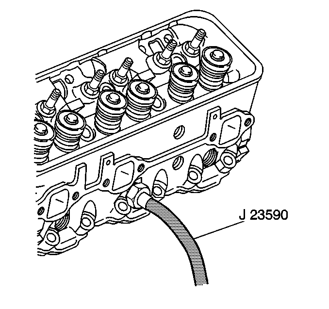
- Install the J 22794
.
Apply compressed air in order to hold the valve in place.
Notice: When using the valve spring compressor, be careful not to scratch or
gouge the valve stem.
- Use the J 38606
in
order to compress the valve spring.

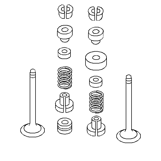
- Remove the valve stem key.
- Remove the valve spring cap.
- Remove the oil shield on the exhaust valves.
- Remove the valve spring.
- Remove the dampener.
- Remove the valve stem O-ring seal.
- Remove the intake valve stem oil seal.
Installation Procedure
Notice: Use hand pressure only when installing the valve stem oil seal using
the J 41512. Using too much force may cause damage to the
oil seal and possibly lead to excessive oil consumption.
- Use the following procedure in order to install the intake valve stem
oil seal:
| 1.1. | Place the oil seal over the valve stem so that the seal contacts
the valve guide. |
| 1.2. | Use the J 41512
in order to push the valve stem oil seal over the valve guide. |

- Install the valve stem O-ring seal.
- Install the valve spring dampener.
- Install the valve spring.
- Install the valve spring oil shield on the exhaust valve.
- Install the valve cap.
- Use the in order to compress the valve spring.
- Use the following procedure in order to install the valve stem
key:
| 8.1. | Use grease in order to hold the key in place while disconnecting
the J 22794
. |
| 8.3. | Ensure that the key seats properly in the upper groove of the
valve stem. |
| 8.4. | Tap the end of the stem with a plastic-faced hammer in order to
seat the key. |
- Install the spark plug.
Tighten
Tighten the spark plug to 27 N·m (20 lb ft).
Notice: Use the correct fastener in the correct location. Replacement fasteners
must be the correct part number for that application. Fasteners requiring
replacement or fasteners requiring the use of thread locking compound or sealant
are identified in the service procedure. Do not use paints, lubricants, or
corrosion inhibitors on fasteners or fastener joint surfaces unless specified.
These coatings affect fastener torque and joint clamping force and may damage
the fastener. Use the correct tightening sequence and specifications when
installing fasteners in order to avoid damage to parts and systems.

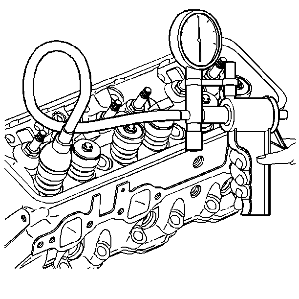
- Use the following procedure in order to inspect the valve stem O-ring
seal for leaks:
| 10.1. | Place the J 23738-A
over the end of the valve stem and against the valve cap. |
| 10.3. | Ensure that no air leaks past the valve stem O-ring. |
- Measure the valve spring installed height.
- Install the valve rocker arms and pushrods. Refer to
Valve Rocker Arm and Push Rod Replacement
.


