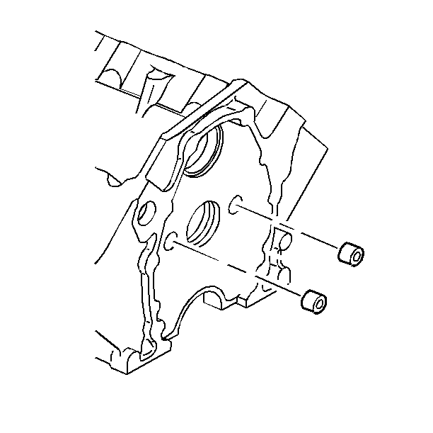
- Use the following procedure in order to disassemble the engine oil gallery
plugs and cooling jacket plugs:
| 1.1. | Obtain a suitable self threading screw. |
| 1.2. | Drill a hole into the plug. |
| 1.3. | Install the self-threading screw. |
| 1.4. | Use the screw in order to pry out the plug. |
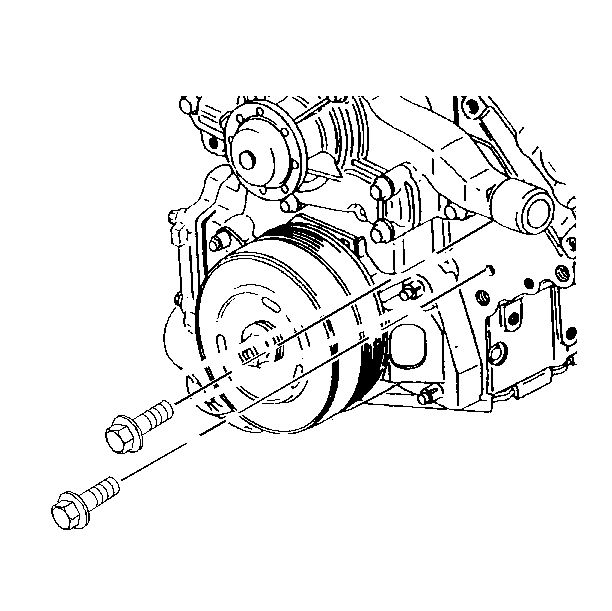
- Disassemble the coolant drain plugs.
- Disassemble the camshaft bearings.
Notice: Caustic cleaning solution destroys the bearing material. All bearings
must be replaced after cleaning with a caustic solution. Do not clean bearing
material or aluminum parts with caustic solutions.
- Clean the sealing material from the mating surfaces.
- Boil the cylinder block in caustic solution.
- Flush the cylinder block with clean water or steam.
- Clean the oil passages.
- Clean all blind holes.
- Spray the cylinder bores and the machine surfaces with engine
oil.
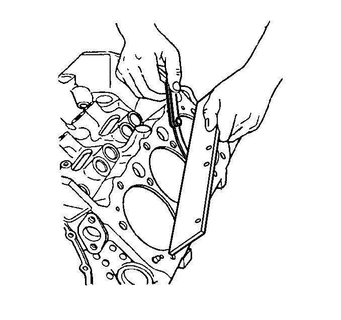
- Use a straight edge and a feeler gage in order to inspect the deck surface
for flatness. Carefully machine minor irregularities. Replace the block if
more than a 0.254 mm (0.010 in) must be removed.
- Inspect the oil pan rail for nicks. Inspect the front cover attaching
area for nicks. Use a flat mill file in order to remove any nicks.
Notice: A broken flywheel may result if the transmission case mating surface
is not flat.
- Inspect the mating surfaces of the transmission case.
- Temporarily install the crankshaft. Measure the crankshaft flange
runout.
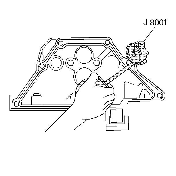
- Use the following procedure in order to measure the cylinder block flange
runout at the six mounting hole bosses:
| 14.1. | Hold the gauge plate flat against the crankshaft flange. |
| 14.2. | Place the dial indicator stem on the transmission mounting bolt
hole boss. Set the indicator to 0. |
| 14.3. | Record the readings obtained from all of the bolt hole bosses.
The measurements should not vary more than 0.254 mm (0.010 in). |
| 14.4. | Recheck the crankshaft flange runout if the readings vary more
than 0.254 mm (0.010 in). |
- Inspect the threaded holes. Clean the holes with a tap. If necessary,
drill out the holes and install thread inserts. Refer to Thread Repair
.
Important: Recondition the cylinder block with the main bearing caps and the main
side bolts installed and tightened to specification.
- Ensure that the main bearing caps are installed correctly. The arrows
should point toward the front of the engine.
- Inspect the bearing bores. Use a bore gauge in order to measure the
bore concentricity and alignment at the following locations:
| • | Replace the cylinder block if the bores are out of specification. |
| • | If the outside of the bearing inserts display minor high spots,
remove the bearing inserts carefully. |
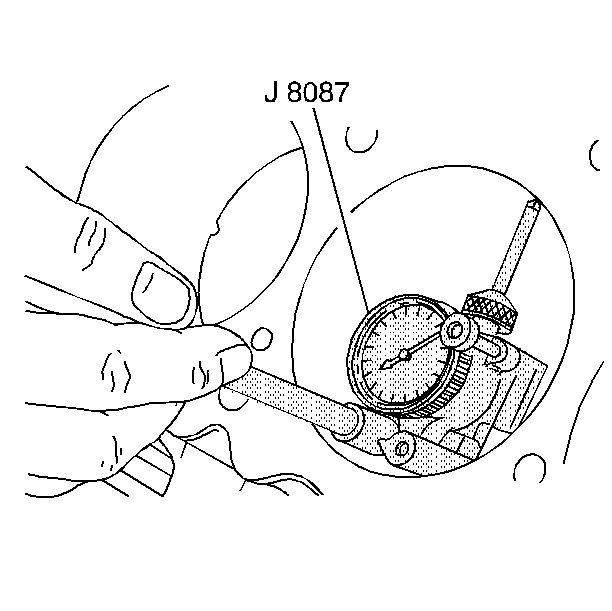
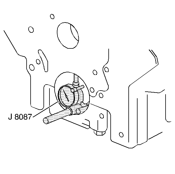
- Use the J 8087
in order
to inspect the cylinder bores. Inspect for the following items:
Important: If the bore is worn beyond the limits, refit the bore with oversized
pistons. Select the smallest available oversize piston. Refer to Piston Selection
- Leave sufficient material in order to allow honing when fitting the
piston.
- If the bore is glazed but serviceable, break the glaze lightly
with a hone. Replace the piston rings.
- Make sure the honing stones are clean, sharp and straight. Move
the hone slowly up and down in order to create a cross-hatch pattern. Clean
the bore with soap and water. Dry the bore. Rub the bore with clean engine
oil. Remeasure the bore.

- Assemble the engine oil gallery plugs and the coolant jacket plugs.
Apply a GM approved sealer or the equivalent.
- Assemble the coolant drain plug.
Tighten
Tighten the coolant drain plug to 18 N·m (13 lb ft).
Notice: Use the correct fastener in the correct location. Replacement fasteners
must be the correct part number for that application. Fasteners requiring
replacement or fasteners requiring the use of thread locking compound or sealant
are identified in the service procedure. Do not use paints, lubricants, or
corrosion inhibitors on fasteners or fastener joint surfaces unless specified.
These coatings affect fastener torque and joint clamping force and may damage
the fastener. Use the correct tightening sequence and specifications when
installing fasteners in order to avoid damage to parts and systems.
- Assemble the camshaft bearings.


