Disassemble Procedure
Tools Required
Important: During disassembly, ensure that the valve train components are kept
together and identified so that they can be reinstalled in their original
locations and with the same mating surfaces as when removed.
- Use the J 38606
in
order to compress the valve spring.

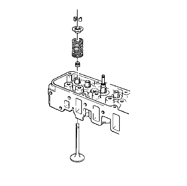
- Disassemble the valve keys.
- Disassemble the valve cap and spring.
- Pry up on the bottom of the seal with a suitable tool in order
to disassemble the valve stem oil seal.
Assemble Procedure
Tools Required
| • | J 41512 Valve
Guide Seal Installer |
Notice: Use hand pressure only when installing the valve stem oil seal using
the J 41512. Using too much force may cause damage to the
oil seal and possibly lead to excessive oil consumption.

- Assemble the valves. Valves are available for sevice in standard size
and 0.010 inch oversize.
- Place the oil seal over the valve stem so that the seal begins
to contact the valve guide.
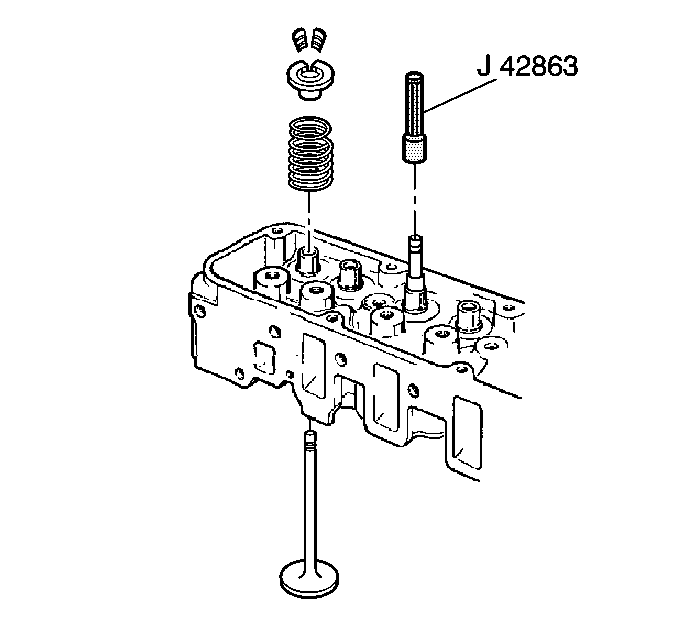
- Use the J 41512
in
order to push the valve stem oil seal over the valve guide.
- Use the J 38606
in
order to assemble the valve spring and the valve cap.
- Assemble the valve keys.
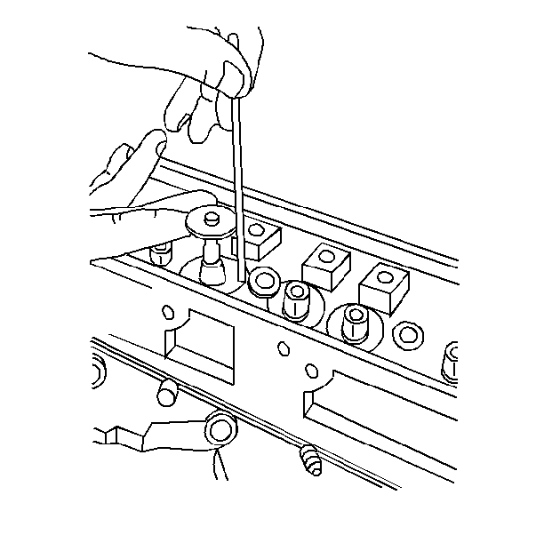
- Use the following procedure in order to measure the valve stem
height:
| 6.1. | Place the valve in the guide. Hold the valve in the closed position. |
| 6.2. | Use a steel machinists' rule in order to measure the valve stem.
Measure from the machined spring seat to the valve tip. |
| 6.3. | The measurement should be 49-50 mm (1.93-1.97 in). |
Important: The lowering of the valve seat or the valve face causes excessive valve
spring installed height. Wear and grinding cause lowering. Add shims in order
to correct the valve spring installed height.

- Use the following procedure in order to measure the valve spring installed
height:
| 7.1. | Place the valve in the guide. |
| 7.2. | Install the valve spring cap. Install the valve cap key. |
| 7.3. | Pull up on the valve spring retainer in order to seat the retainer. |
| 7.4. | Use a steel machinists' rule in order to measure the distance
from the machined spring seat to the spring side of the cap. |
| 7.5. | The measurement should be 42-44 mm (1.69-1.75 in). |
If the measurement is not within specifications add shims under the
valve spring as necessary.


