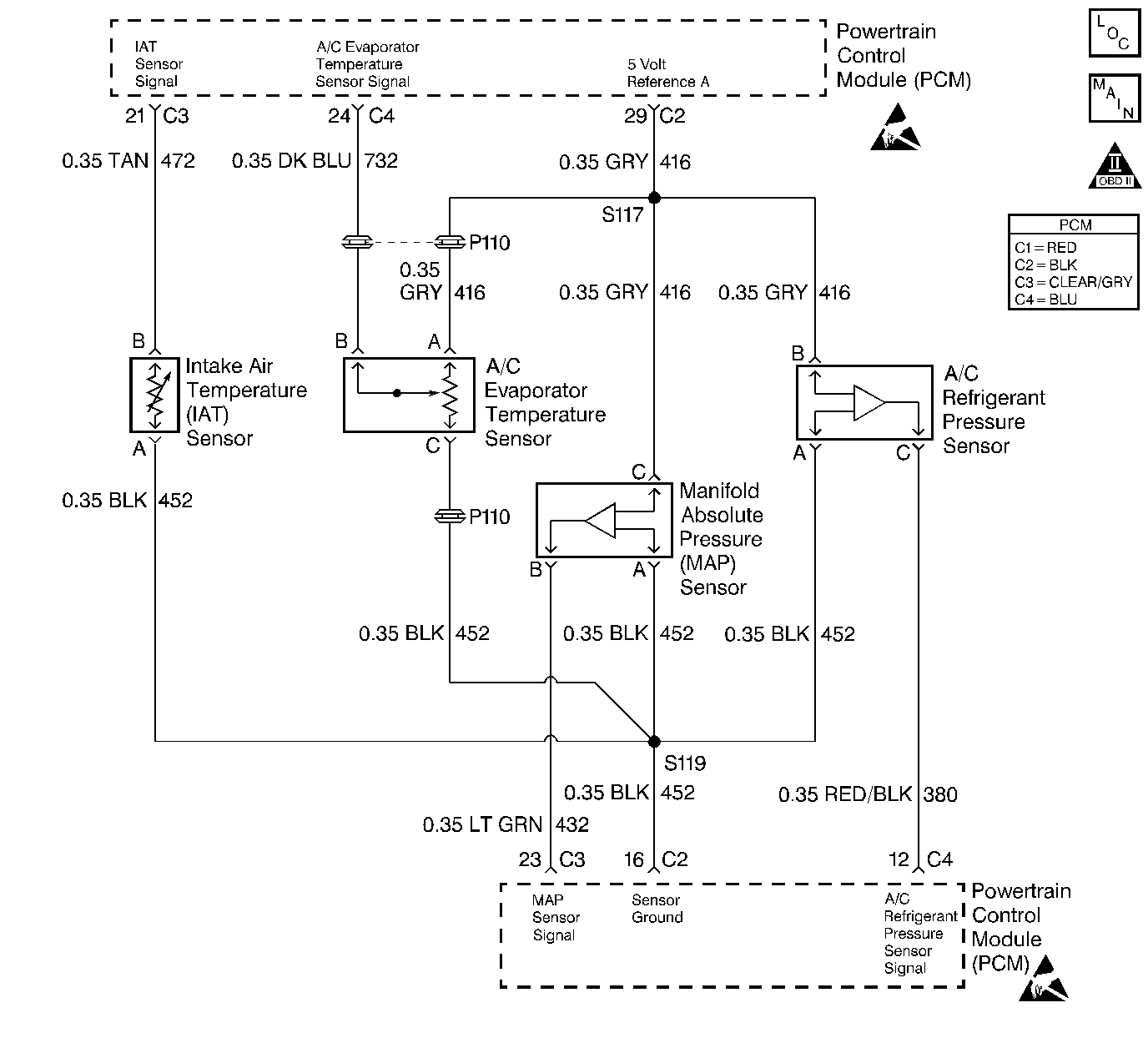
Circuit Description
The PCM uses the A/C Evaporator Temperature Sensor signal to prevent evaporator icing. By cycling the A/C compressor clutch based on this input, the PCM maintains higher A/C efficiency. The sensor is mounted on the evaporator case inside the vehicle and has a remote probe which is in contact with the evaporator core. This sensor has an unusual method of operation. The sensor is a three wire sensor having ground, signal and 5 volt reference circuits. However, the sensor has internal circuitry that uses the 5 volt circuit as a power supply rather than a reference voltage, and the signal circuit is pulled up to 5 volts within the PCM (similar to ECT or IAT). The sensors internal circuitry pulls the signal circuit to ground as evaporator temperature rises. Therefore, high evaporator temperature causes low signal voltage and low temperature causes high signal voltage. The PCM monitors the signal voltage and controls compressor operation accordingly.
Conditions for Setting the DTC
| • | The PCM is commanding the A/C clutch ON. |
| • | The PCM detects evaporator temperature above 52°C (126°F). |
| • | All conditions met for 5 seconds. |
Action Taken When the DTC Sets
| • | DTC P1533 will be stored in the PCM memory when the diagnostic runs and fails. |
| • | The Malfunction Indicator Lamp (MIL) will not illuminate. |
| • | The PCM will record operating conditions at the time the diagnostic fails. This information will be stored in Failure Records. |
Conditions for Clearing the MIL/DTC
| • | If no failures are reported by this or any other non-emission related diagnostic. |
| • | A last test failed (Current DTC) will clear when the diagnostic runs and does not fail. |
| • | PCM battery voltage is interrupted. |
| • | Using a Scan tool. |
Diagnostic Aids
Reviewing the Freeze Frame/Failure Records Buffer data will determine when the malfunction occurred. Drive the vehicle under the conditions that were noted. If the Freeze Frame / Failure Records Buffer data indicates the malfunction occurred during extreme operating conditions (RPM, temperature, Baro, etc.), it may indicate that the conditions can not be duplicated. Inspect all related wiring and connectors including the connections at the PCM. These may cause an intermittent malfunction. Check for damaged, corroded or pushed out terminals.
Test Description
Number(s) below refer to step numbers on the diagnostic table.
-
Low signal voltage (such as a short to ground) will cause the scan tool to indicate high evaporator temperature. High signal voltage (a short to voltage or an open signal circuit) will cause the scan tool to indicate low temperature.
-
Low signal voltage (such as a short to ground) will cause the scan tool to indicate high evaporator temperature. High signal voltage (a short to voltage or an open signal circuit) will cause the scan tool to indicate low temperature.
Step | Action | Value(s) | Yes | No |
|---|---|---|---|---|
1 | Was the Powertrain On-Board Diagnostic (OBD) system check performed? | -- | Go to Powertrain Powertrain On Board Diagnostic (OBD) System Check | |
2 |
Does the scan tool indicate the temperature shown? | 52°C (126°F) | ||
3 | Does the scan tool indicate the temperature shown? | -17°C (2°F) | Go to Diagnostic Aids | |
4 | Disconnect the A/C evaporator temperature sensor harness connector. Does the scan tool indicate the temperature shown? | -17°C (2°F) | ||
5 |
Does the DVM indicate the voltage shown? | 5.0V | ||
6 | Using a DVM (J 39200), measure the voltage between the 5 volt reference circuit and the ground circuit in the evaporator temperature sensor harness connector. Does the DVM indicate the voltage shown? | 5.0V | ||
7 |
Does the DVM indicate the voltage shown? | 5.0V | ||
8 | With the fused jumper wire still connected, monitor the A/C evaporator temperature with the scan tool. Does the scan tool indicate the temperature shown. | 52°C (126°F) | ||
9 | Using a DVM (J 39200), measure the voltage between the signal circuit and the ground circuit in the evaporator temperature sensor harness connector. Does the DVM indicate the voltage shown? | 0V | ||
10 | Repair the 5 volt reference circuit. Is the action complete? | -- | -- | |
11 | Repair the open ground circuit. Is the action complete? | -- | -- | |
12 | Repair the open signal circuit. Is the action complete? | -- | -- | |
13 | Repair the signal circuit for a short to ground. Is the action complete? | -- | -- | |
14 | Repair the signal circuit for a short to voltage. Is the action complete? | -- | -- | |
15 | Repair the 5 volt reference and the signal circuit for being shorted together. Is the action complete? | -- | -- | |
16 | Replace the evaporator temperature sensor. Is the action complete? | -- | -- | |
17 |
Does the scan tool indicate that this test ran and passed? | -- | ||
18 | Using the scan tool, select Capture Info, Review Info. Are any DTCs displayed that have not been diagnosed? | -- | Go to the applicable DTC table | System OK |
