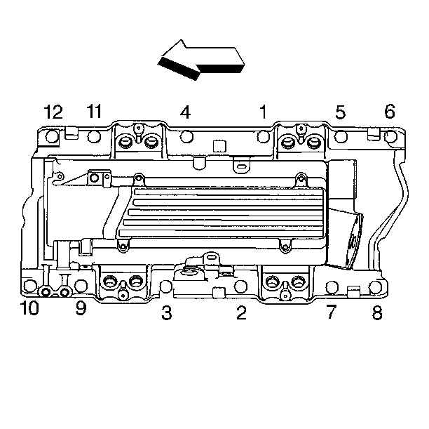
Removal Procedure
Important: This vehicle uses a sequential multiport fuel injected engine. The fuel
injector connectors must be connected to their appropriate fuel injector,
or engine performance and exhaust emissions may be seriously affected. The
fuel injector connectors are numbered to match their correct fuel injector
for that cylinder. If the fuel injector connector numbers can not be identified,
refer to SECTION 8A for correct fuel injector connector wire to fuel injector
for each cylinder.

- Disconnect the negative battery cable.
- Relieve the fuel system pressure. Refer to Fuel Pressure Relief Procedure
in Engine Controls.
- Drain the coolant. Refer to SECTION 6B.
- Disconnect the Intake Air Temperature (IAT) sensor connector.
- Remove the air intake duct from the throttle body and Mass AirFlow
(MAF) sensor.
- Disconnect the clips attaching the fuel lines to the throttle
body linkage cover.
- Disconnect the wiring harness connectors from the fuel injectors.
- Disconnect the clips attaching the wiring harness to the fuel
rail.
- Lay the left and the right wiring harnesses aside.
- Remove the accelerator control/cruise control servo cable adjuster,
if equipped.
- Remove the accelerator bracket and the accelerator cables from
the throttle body.

- Remove the secondary air injection diverter valve hoses.

- Remove the fuel pipe connectors from the fuel rail.
- Remove the fuel rail bolts.

- Remove the fuel pressure regulator vacuum tube.
- Remove the fuel rail from the intake manifold and lay aside.

- Remove the EGR valve vacuum harness.

- Remove the crankcase vent hose.

- Remove the Exhaust Gas Recirculation (EGR) control valve relay nut and
control valve relay.

- Remove the emission canister purge solenoid bracket nut and the solenoid.
- Remove the EGR valve nuts and the valve.
- Remove the EGR valve pipe nut and the stud.

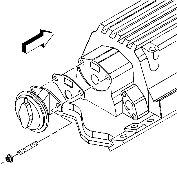
- Remove the secondary air injection pipe from the right exhaust manifold.

- Remove the generator rear brace. Refer to SECTION 6D3.
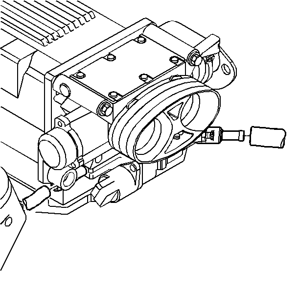
- Remove the coolant hoses from the throttle body.
- Disconnect the connectors from the Throttle Position (TP) sensor
and the Idle Air Control (IAC) valve.

- Remove the following parts:
| • | The throttle body bolts |
| • | The throttle body gasket |

- Remove the intake manifold bolts and studs.
- Remove the intake manifold and the gaskets.
- Discard the intake manifold gaskets.
- Clean the following parts:
| • | The intake manifold bolts and the studs |
| • | The intake manifold sealing surfaces |
Installation Procedure
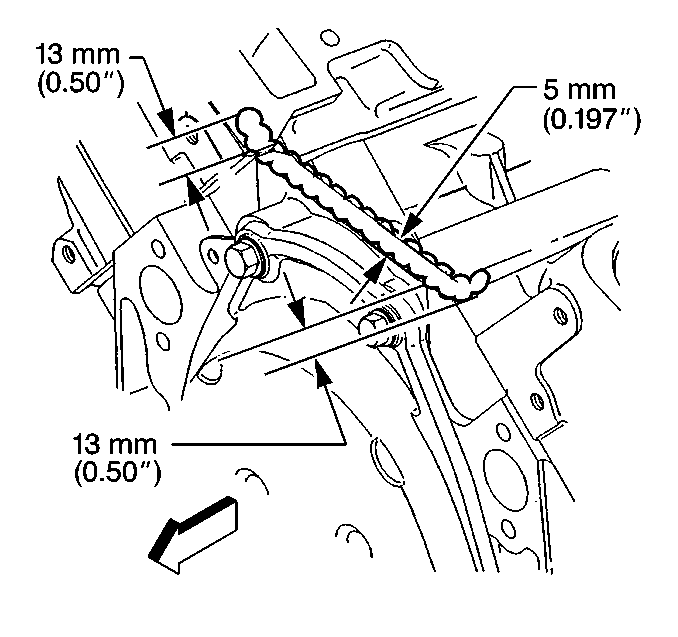
- Apply a 5 mm (0.189 in) bead of RTV sealer, GM P/N 12346192
or the equivalent, to the front of the engine block. Extend the bead 13 mm
(0.5 in) up each cylinder head in order to the seal and retain the
gaskets.
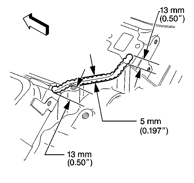
- Apply a 5 mm (0.189 in) bead of RTV sealer, GM P/N 12346192
or the equivalent, to the rear of the engine block. Extend the bead 13 mm
(0.5 in) up each cylinder head in order to the seal and retain the
gaskets.
- Install the intake manifold with the new gaskets.
- Install the intake manifold bolts and the studs.
Tighten
| • | Tighten the intake manifold bolts and the studs in a first pass
to 10 N·m (89 lb in) in sequence. |
| • | Tighten the intake manifold bolts and studs in the second pass
to the final specifications of 50 N·m (37 lb ft)
in sequence. |
- Install the throttle body, gasket, and bolts.
Tighten
Tighten the throttle body bolts to 25 N·m (18 lb ft).
- Connect the connectors to the Throttle Position (TP) sensor and
the Idle Air Control (IAC) sensor.
- Install the coolant hoses to the throttle body.
- Install the generator rear brace. Refer to SECTION 6D3.
- Install the secondary air injection pipe to the exhaust manifold.
Tighten
Tighten the secondary air injection pipe to 55 N·m (41 lb ft).
- Install the EGR valve pipe, stud and the nut.
- Install the EGR valve and the nuts.
Tighten
| • | Tighten the EGR valve pipe stud to 12 N·m (106 lb in). |
| • | Tighten the EGR valve pipe nut to 25 N·m (18 lb ft). |
| • | Tighten the EGR valve nuts to 30 N·m (22 lb ft). |
| • | Tighten the EGR pipe to exhaust manifold bolt to 30 N·m
(22 lb ft). |
- Install the EGR control valve relay and the nut.
Tighten
Tighten the EGR control valve relay nut to 25 N·m (18 lb ft).
- Install the emission canister purge solenoid and the bracket bolt.
Tighten
Tighten the emission canister purge solenoid bracket bolt to 6 N·m
(53 lb in).
- Connect the EGR valve vacuum harness.
- Install the fuel pressure regulator vacuum tube.
- Install the fuel rail to the intake manifold.
- Install the fuel rail bolts.
Tighten
Tighten the fuel rail bolts to 10 N·m (89 lb in).
- Connect clip attaching the wiring harness to the fuel rail.
- Install the fuel pipe connectors to the fuel rail.
- Install the secondary air injection diverter valve hoses.
- Install the accelerator cable bracket, bolts, cables and cover.
Tighten
Tighten the accelerator cable bracket bolts to 12 N·m (106 lb in).
- Install the accelerator control/cruise control servo cable adjuster,
if equipped.
- Install the wiring harness connectors to the fuel injectors.
- Connect clips attaching the fuel lines the throttle linkage cover.
- Connect the Intake Air Temperature (IAT) sensor and Mass AirFlow
(MAF) sensor connectors.
- Install the negative battery cable.
- Refill with coolant. Refer to SECTION 6B.
