Fuel Hose and Pipes Rear Fuel and EVAP Pipes
Removal Procedure

- Disconnect the negative battery cable.
- Relieve the fuel system pressure. Refer to the Fuel Pressure Relief Procedure
.
- Drain the fuel tank. Refer to
Fuel Tank Draining
.
- Raise the vehicle.
- Clean all fuel and EVAP pipe and hose connections and the surrounding
areas before disconnecting in order to avoid possible contamination of the
fuel system.
- Remove the fuel tank. Refer to Fuel Tank Replacement
.
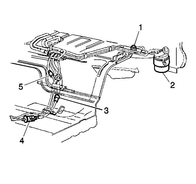
- Disconnect the rear fuel feed pipe (3) and the return pipe (5)
from the chassis fuel pipe and the fuel filter (4). Refer to
Servicing Quick Connect Fittings
.
- Disconnect the EVAP hoses from the EVAP pressure control valve
(1) and the EVAP canister (2).
Installation Procedure

- Connect the EVAP hoses to the EVAP pressure control valve (1) and the
EVAP canister (2).
- Connect the rear fuel feed pipe (3) and the return pipe (5) to
the chassis fuel pipe and the fuel filter (4).
- Install the fuel tank. Refer to Fuel Tank Replacement
.
- Lower the vehicle.
- Refill the fuel tank.
- Connect the negative battery cable.
- Tighten the fuel filler cap.
- Inspect for leaks.
| 8.1. | Turn the ignition switch ON for two seconds. |
| 8.2. | Turn the ignition switch OFF for ten seconds. |
| 8.3. | Turn the ignition switch ON. |
| 8.4. | Inspect for fuel leaks. |
Fuel Hose and Pipes Chassis Fuel and EVAP Pipes
Removal Procedure

- Disconnect the negative battery cable.
- Relieve the fuel system pressure. Refer to the Fuel Pressure Relief Procedure
.
- Drain the fuel tank. Refer to
Fuel Tank Draining
.
- Raise the vehicle.
- Clean all the fuel and EVAP pipe and hose connections and the
surrounding areas before disconnecting in order to avoid possible contamination
of the fuel system.
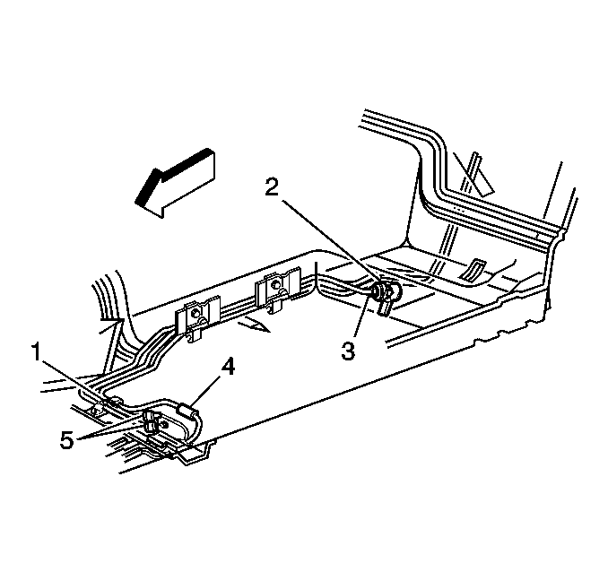
- Disconnect the engine compartment connecting fuel feed and return
pipes (5) and the EVAP pipe (4) from the chassis fuel and EVAP pipes. Refer
to
Servicing Quick Connect Fittings
.
- Disconnect the fuel feed pipe from the outlet side (3) of the
fuel filter (2). Discard the O-ring.
- Disconnect the fuel return pipe and the EVAP pipe from the rear
fuel and EVAP pipes. Refer to
Servicing Quick Connect Fittings
.
- Remove the fuel pipe attaching hardware and the fuel pipes. Note
the position of the fuel pipes for installation.
- Inspect the pipes for bends, kinks, and cracks. Repair or replace
the pipes as required.
Repair Procedure
When repairing the fuel or EVAP pipes with hoses, always replace them
with original equipment or parts meeting GM specifications. Use only reinforced
fuel resistant hose which is identified with the word Fluoroelastomer or GM
6163-M on the hose. The inside hose diameter must match the outside
pipe diameter.
Do Not use rubber hose within 100 mm (4 in) of any part
of the exhaust system or within 254 mm (10 in) of the catalytic
converter.
A minimum of 13 mm (½ in) clearance must be maintained
around sharp edges such as flanges, pinch welds, etc., in order to prevent
contact and chafing. A minimum of 19 mm (¾ in) clearance
must be maintained around all moving parts.
Cut the ends of the pipe remaining on the car square with a tube cutter.
Using the first step of a double flaring tool, form a bead on the end of both
pipe sections. If the pipe is too corroded to withstand the beading operation
without damage, the pipe should be replaced. If a new section of pipe is used,
form a bead on both ends of the pipe also.
Use screw type hose clamps. Slide the clamps onto the pipe and push
the hose 51 mm (2 in) onto each portion of the fuel pipe.
If more than a 6 in length of pipe is removed, use a combination
of steel pipe and hose so that the total hose lengths, including the 100 mm
(4 in) additional length will not be more than 254 mm (10 in)
long. Follow the same routing as the original pipe.
Installation Procedure

Important:
| • | When replacing the fuel or EVAP pipes, always replace them with
original equipment or parts that meet the GM specifications for those parts.
The replacement pipes must have the same type of fittings as the original
pipes in order to ensure the integrity of the connection. |
| • | Do Not use copper or aluminum tubing to replace steel tubing.
Only tubing meeting the 124-M specification or its equivalent is capable
of meeting all pressure, corrosion and vibration characteristics necessary
to ensure the durability standard required. |
- Position the new or repaired fuel pipe or pipes in the body clips as
noted during removal. Install the attaching hardware.
- Position the new O-ring on the fuel feed pipe and connect the
pipe to the outlet side (3) of the fuel filter (2).
Tighten
Tighten the fuel feed pipe fitting to 30 N·m (22 lb
ft).
Refer to the
Notice: Use the correct fastener in the correct location. Replacement fasteners
must be the correct part number for that application. Fasteners requiring
replacement or fasteners requiring the use of thread locking compound or sealant
are identified in the service procedure. Do not use paints, lubricants, or
corrosion inhibitors on fasteners or fastener joint surfaces unless specified.
These coatings affect fastener torque and joint clamping force and may damage
the fastener. Use the correct tightening sequence and specifications when
installing fasteners in order to avoid damage to parts and systems.
in General Information.- Connect the fuel return pipe and the EVAP pipe to the rear fuel
and EVAP pipes. Refer to
Servicing Quick Connect Fittings
.
- Connect the chassis fuel and EVAP pipes to the engine compartment
connecting fuel feed and return pipes (5) and the EVAP pipe (4). Refer to
Servicing Quick Connect Fittings
.
- Lower the vehicle.
- Refill the fuel tank.
- Tighten the fuel filler cap.
- Connect the negative battery cable.
- Inspect for leaks.
| 9.1. | Turn the ignition switch ON for two seconds. |
| 9.2. | Turn the ignition switch OFF for ten seconds. |
| 9.3. | Turn the ignition switch ON. |
| 9.4. | Inspect for fuel leaks. |
Fuel Hose and Pipes Engine Fuel and EVAP Pipes
Removal Procedure

- Disconnect the negative battery cable.
- Relieve the fuel system pressure. Refer to the Fuel Pressure Relief Procedure
.
- Drain the fuel tank. Refer to
Fuel Tank Draining
.
- Clean all the engine compartment connecting fuel pipe connections
and the surrounding areas before disconnecting in order to avoid possible
contamination of the fuel system.
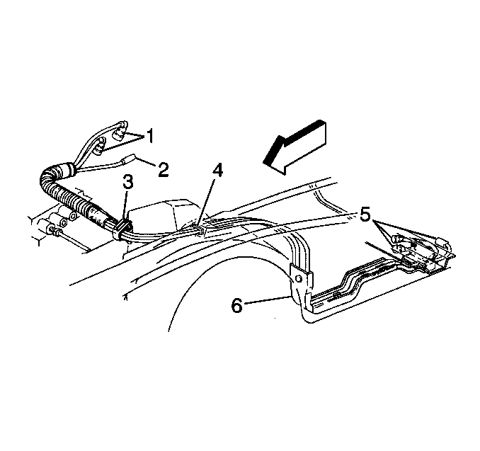
- Disconnect the fuel feed and return pipes (1) and the EVAP pipe
(2) at the engine. Refer to
Servicing Quick Connect Fittings
.
- Disconnect the fuel and EVAP pipes from the routing clip (3).
- Disconnect the fuel and EVAP pipes from the retainer on the accelerator
cable shield.
- Reposition the grommet (4) in the wheelhouse.
- Raise the vehicle.
- Reposition the left front wheelhouse liner panel.

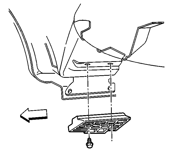
- Remove the fuel feed, return, and EVAP pipe protector.

- Disconnect the fuel and EVAP pipes at the chassis fuel and EVAP pipes
(5). Refer to
Servicing Quick Connect Fittings
.
- Remove the fuel feed, return, and EVAP pipes from the underbody
retainer (6).
Installation Procedure

- Install the fuel and EVAP pipes through the wheelhouse opening.
- Connect the fuel and EVAP pipes at the chassis fuel and EVAP pipes
(5).
- Install the fuel feed, return, and EVAP pipes into the underbody
retainer (6).

- Install the fuel and EVAP pipe protector.

- Install the left front wheelhouse liner panel.
- Lower the vehicle.
- Install the fuel and EVAP pipes to the routing clip (3).
- Install the fuel and EVAP pipes into the retainer on the accelerator
cable shield.
- Install the grommet (4) in the wheelhouse.
- Connect the fuel feed and return pipes (1) and the EVAP pipe (2)
to the engine.
- Refill the fuel tank.
- Tighten the fuel filler cap.
- Connect the negative battery cable.
- Inspect for leaks.
| 14.1. | Turn the ignition switch ON for two seconds. |
| 14.2. | Turn the ignition switch OFF for ten seconds. |
| 14.3. | Turn the ignition switch ON. |
| 14.4. | Inspect for fuel leaks. |


