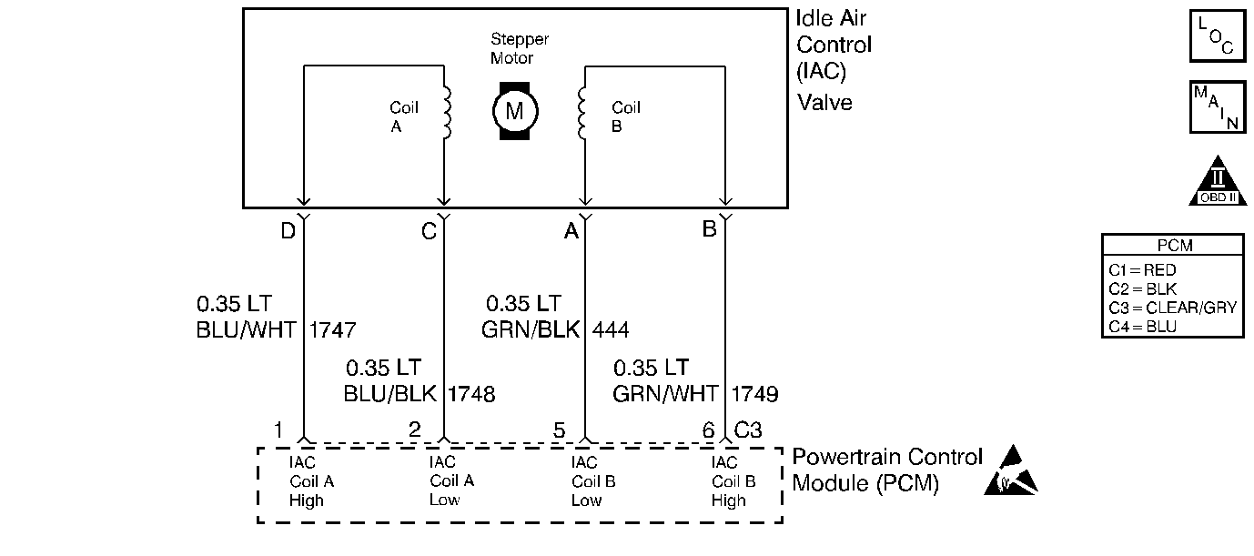
Circuit Description
The Idle Air Control valve is a PCM controlled stepper motor located on the throttle body. The stepper motor drives a valve pintle which protrudes into a passage that bypasses the throttle plates. To decrease idle speed, the PCM commands the IAC valve pintle to extend. As the pintle approaches its seat, bypass air flow is reduced and idle speed decreases. To increase idle speed, the PCM retracts the IAC valve pintle away from its seat, allowing more air to bypass the throttle plates. One of the PCMs uses for the IAC system is to maintain a desired idle speed, which can vary depending on input to the PCM and other criteria. If the PCM detects engine speed is outside the IAC systems range of control at idle, it will perform an active test while the vehicle is being driven. During this test the PCM commands the IAC valve to move while monitoring MAF. If no change in MAF is detected, the IAC valve is not functioning. If idle RPM was out of IAC System control and the IAC valve does not operate, DTC P1508 is set. If the expected change in MAF had been detected, IAC valve operation would have been verified. Since idle RPM was out of IAC System control but the IAC valve was operational, DTC P0506 would be set.
Conditions for Setting the DTC
| • | DTCs P0107, P0108, P0122, P0123, P0174, P0175, P0300, P0325 not set. |
| • | Engine running for at least 25 seconds. |
| • | Coolant temperature greater than 60°C (140°F) |
| • | IAT greater than -10°C (14°F) |
| • | Baro greater than 77 kPa |
| • | System voltage between 10 and 17 volts |
| • | Vehicle speed less than 1 mph |
| • | Throttle Angle 0% |
| • | Idle speed below desired RPM |
| • | Conditions met for 1 sec |
Then
| • | Vehicle speed is between 20 and 77 mph. |
| • | MAF between 13 and 35 gm/s |
| • | TPS steady |
| • | RPM steady |
| • | Conditions met for 5 seconds |
The active test will then be performed.
| • | If a 6 gm/s change in MAF is detected, DTC P0506 will be set. |
| • | If a 6 gm/s change in MAF is not detected, DTC P1508 will be set. |
Action Taken When the DTC Sets
| • | The PCM will illuminate the Malfunction Indicator Lamp (MIL) on the second consecutive drive trip that the diagnostic runs and fails. |
| • | The PCM will record operating conditions at the time the diagnostic fails. The first time the diagnostic fails, this information will be stored in Failure Records. If the diagnostic reports a failure on the second consecutive drive trip, the operating conditions at the time of failure will be written to Freeze Frame and the Failure record will be updated. |
Conditions for Clearing the MIL/DTC
| • | The PCM will turn the MIL OFF after three consecutive drive trips that the diagnostic runs and does not fail. |
| • | A last test failed (Current DTC) will clear when the diagnostic runs and does not fail. |
| • | A History DTC will clear after forty consecutive warm-up cycles, if no failures are reported by this or any other emission related diagnostic. |
| • | PCM battery voltage is interrupted. |
| • | Using a Scan tool. |
Diagnostic Aids
Using Freeze Frame and/or Failure Records data may aid in locating an intermittent condition. If the DTC cannot be duplicated, the information included in the Freeze Frame and/or Failure Records data can be useful in determining how many miles since the DTC set. The Fail Counter and Pass Counter can also be used to determine how many ignition cycles the diagnostic reported a pass and/or a fail. Operate vehicle within the same freeze frame conditions (RPM, load, vehicle speed, temperature etc.) that were noted. This will isolate when the DTC failed. For intermittents, refer to Symptoms .
Test Description
Number(s) below refer to step numbers on the diagnostic table.
Step | Action | Value(s) | Yes | No | ||||||||
|---|---|---|---|---|---|---|---|---|---|---|---|---|
1 | Was the Powertrain On-Board Diagnostic (OBD) System Check performed? | -- | ||||||||||
Does the engine speed correspond (within 50 RPM) with each command? | -- | Go to Diagnostic Aids | ||||||||||
3 |
Does both of the LEDs on the node light cycle red and green, but never OFF? | -- | ||||||||||
4 |
Important:: During the following test it is possible to overextend the IAC valve pintle until it falls out of the worm drive. If this occurs, manually screw the pintle shaft into the worm drive about 2 turns to get it started, align the keyways on the shaft with the keys in the housing and gradually retract the pintle using the IAC driver tool.
Does the pintle move steadily with each flash of the IAC driver light? | -- | ||||||||||
5 | Check for the following conditions:
Is the action complete? | -- | -- | |||||||||
6 | Check the IAC passages. Is the action complete? | -- | -- | |||||||||
7 | Replace the IAC valve. Refer to Idle Air Control Valve Replacement . Is the action complete? | -- | -- | |||||||||
8 |
Does the scan tool indicate that this test ran and passed? | -- | ||||||||||
9 | Using the scan tool, select Capture Info, Review Info. Are any DTCs displayed that have not been diagnosed? | -- | Go to the applicable DTC table | System OK |
