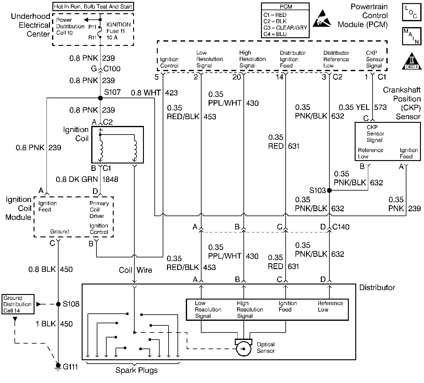
Description
This table assumes that battery condition and engine cranking speed are OK. If not, refer to Engine Electrical for diagnosis. Also, make sure that there is adequate fuel in the tank.
Diagnostic Aids
| • | An EGR valve sticking open can cause a low air/fuel ratio during cranking. |
| • | Unless the engine enters Clear Flood at the first indication of a flooding condition, a no start may result. |
| • | Check the duct work between the Mass Air Flow (MAF) sensor and the throttle body for air leaks. |
| • | A malfunctioning MAF sensor may cause a no start or a stall after start. If this is suspected, disconnect the MAF sensor. The PCM will default to speed density (MAP, IAT, RPM) to calculate load and air flow. If this corrects the condition and the connections are OK, replace the MAF sensor. |
If the steps above check OK, refer to Symptoms .
Test Description
Number(s) below refer to step numbers on the diagnostic table.
Step | Action | Value(s) | Yes | No | ||||||||
|---|---|---|---|---|---|---|---|---|---|---|---|---|
1 | Was the Powertrain On-Board Diagnostic (OBD) System Check performed? | -- | ||||||||||
2 |
Important: An open ignition feed to the injector circuit will cause the engine not to start. Inspect the injector fuse for being open. Also inspect the circuits for opens or grounds. Using the scan tool, select ENG DTC, DTC Info, LAST TST FAIL. Are any of the following DTCs displayed: P0100, P0200, P0601, P0602, P1351, P1361, P1371? | -- | Go to the applicable DTC table | |||||||||
3 | Using the scan tool, check Pass Key status. Does the scan tool indicate OK? | -- | Go to Theft Deterrent System | |||||||||
4 | Using the scan tool, check Eng Cool Temp. Is the Eng Cool Temp on the scan tool should be close to the actual engine temperature? | -- | Go to DTC P0118 Engine Coolant Temperature (ECT) Sensor Circuit High Voltage | |||||||||
5 | Using the scan tool, check Throttle Angle at a closed throttle. Is the Throttle Angle at the specified value? | 0% | Go to DTC P0122 Throttle Position (TP) Sensor Circuit Low Voltage | |||||||||
6 | Using the scan tool, check the Engine Speed while cranking the engine. Is RPM indicated on the scan tool? | -- | ||||||||||
7 | Using Spark Tester J 26792 (ST-125), check for spark while cranking the engine (check 2 wires). Is spark present? | -- | Basic ignition problem. Go to Distributor Ignition (DI) System Check | |||||||||
8 | Using the scan tool, enable the fuel pump. Does the fuel pump operate? | -- | ||||||||||
9 |
Is the fuel pressure within the specified range? | 283-325 kPa (41-47 psi) | Go to Fuel System Diagnosis | |||||||||
10 | Perform the following additional checks:
Was a problem found and corrected? | -- | Go to Hard Start for diagnosis. | |||||||||
11 |
Does the test light illuminate? | -- | ||||||||||
Using DVM J 39200 measure resistance from harness connector terminal D to ground. Does the DVM display the specified value (or lower)? | 5 ohms | |||||||||||
13 |
Does the DVM display the specified value (or lower)? | 5 ohms | ||||||||||
14 | Using DVM J 39200, measure the resistance from the distributor connector terminal C to ground. Does the DVM display infinite resistance? | -- | ||||||||||
15 |
Does the DVM display the specified value (or lower)? | 5 ohms | ||||||||||
16 | Repair the open ignition feed circuit to the distributor. Is the action complete? | -- | -- | |||||||||
17 | Repair the short to ground in the ignition feed circuit to the distributor. Is the action complete? | -- | -- | |||||||||
18 | Repair the distributor reference low circuit (ground). Is the action complete? | -- | -- | |||||||||
19 | Replace the distributor. Refer to Ignition System. Is the action complete? | -- | -- | |||||||||
20 | Check the connections at the PCM. Was a problem found and corrected? | -- | ||||||||||
21 |
Important:: Replacement PCM must be programmed. Refer to Powertrain Control Module Replacement/Programming . Replace the PCM. Is the action complete? | -- | -- | |||||||||
22 |
Does the engine start and continue to run? | -- | ||||||||||
23 |
Are any DTCs displayed? | -- | Go to the applicable DTC table | |||||||||
24 | Using the scan tool, select Capture Info, Review Info. Are any DTCs displayed that have not been diagnosed? | -- | Go to the applicable DTC table | System OK |
