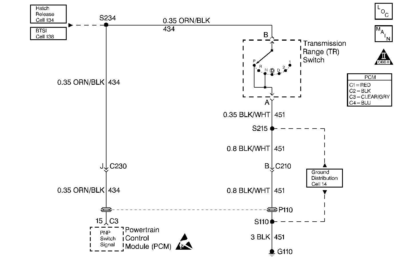
Circuit Description
The Park/Neutral Position (PNP) switch contacts are closed to ground in park and neutral. The PCM applies a voltage (about 12.0 Volts) to the switch. When the gear selector is in park or neutral the PNP switch is closed and the PCM senses low signal voltage (low engine load). When the gear selector is in reverse or a drive range, the PNP switch opens, and the PCM senses high signal voltage (high engine load). The PCM will increase the idle air rate to compensate for the additional load on the engine when the transmission is in gear.
Some of the PCMs other uses for the PNP signal are:
| • | Vehicle Speed Sensor (VSS) diagnostics |
| • | Exhaust Gas Recirculation (EGR) operation |
Diagnostic Aids
| • | A PNP switch that does not close or an open circuit may cause the engine idle speed to drop when the vehicle is shifted into gear. |
| • | A switch that will not open or the signal circuit shorted to ground will cause the EGR system to be inoperative, possibly resulting in excessive spark knock. |
| • | Inspect all related wiring and connectors including the connections at the PCM. These may cause an intermittent malfunction. Check for damaged, corroded or pushed out terminals. |
Step | Action | Value(s) | Yes | No |
|---|---|---|---|---|
1 | Was the Powertrain On-Board Diagnostic (OBD) System Check performed? | -- | Go to Powertrain OBD System Check | |
2 |
Does the scan tool indicate Park/Neutral (P-N----)? | -- | ||
3 | Shift transmission into drive. Does the scan tool should indicate Drive (-R-OD21). | -- | No trouble found. Go to Diagnostic Aids | |
4 |
Does the scan tool indicate Park/Neutral (P-N----)? | -- | ||
5 | Using a fused jumper wire connected to ground, probe terminal B in the PNP switch harness connector. Does the scan tool indicate Park/Neutral (P-N----)? | -- | ||
6 |
Does The test light illuminate? | -- | ||
7 | Disconnect the Park/Neutral Position switch connector. Does the scan tool indicate Drive (-R-OD21)? | -- | ||
8 |
Does the scan tool indicate Drive (-R-OD21)? | -- | ||
9 | Check for faulty connections at the PCM. Was the condition found and corrected? | -- | ||
10 | Check for faulty connections at the PNP switch or PNP switch out of adjustment. Was the condition found and corrected? | -- | ||
11 | Repair open PNP signal circuit. Is the repair completed? | -- | -- | |
12 | Repair PNP signal circuit shorted to ground. Is the repair completed? | -- | -- | |
13 | Repair open PNP ground circuit. Is the repair completed? | -- | -- | |
14 | Replace PNP switch. Is the repair completed? | -- | -- | |
15 | Replace the PCM. Is the repair completed? | -- | -- | |
16 | Operate the vehicle within the conditions under which the original symptom was noted. Does the system now operate properly? | -- | System OK |
