High Speed Driveline Vibration Causing Transmission Rear Seal Failure

| Subject: | CAMPAIGN 99010 -- HIGH SPEED DRIVELINE VIBRATION CAUSING TRANSMISSION REAR SEAL FAILURE |
| Models: | 1998/1999 EXPORT CHEVROLET CAMARO EQUIPPED WITH 3.8 L ENGINE (RPO L36 -- VIN CODE K) AND AUTOMATIC TRANSMISSION (RPO M30) |
Defect Involved
General Motors has decided that certain 1998 and 1999 export (RPO QII) Chevrolet Camaro F-Car model vehicles equipped with 3.8 L V6 (RPO L36) engines and automatic (RPO M30) transmissions may exhibit a condition in which vehicle speed in excess of 125 MPH (200 KPH) for an extended period of time may cause the one-piece driveline propshaft to vibrate at the slip yoke. This, in turn, may damage the transmission rear housing seal bushing, so that the seal backs out and causes transmission fluid leakage.
To prevent the possibility of this condition occurring, dealers are to replace the one-piece propshaft with a two-piece propshaft. Also, dealers are to replace the transmission extension housing with an improved extension housing, if the vehicle is not already equipped with the improved extension housing. Dealers will also have to replace the torque arm assembly with a new torque arm assembly in order to support the two-piece propshaft.
Vehicles Involved
Involved are certain 1998 and 1999 Export Chevrolet Camaro (F-Car) model vehicles equipped with 3800 Series II (L36) V6 engines, and automatic (M30) transmissions, and built within the following VIN breakpoints:
Year | Division | Model | Plant | From | Through |
|---|---|---|---|---|---|
1998 | Chevrolet | Camaro | Ste-Therese | W2100021 | W2151728 |
1999 | Chevrolet | Camaro | Ste-Therese | X2100359 | X2112492 |
Important: Dealers should confirm vehicle eligibility through DCS Screen 445 or your V.I.N. listing prior to beginning campaign repairs. (Not all vehicles within the above breakpoints may be involved.) Only affected VIN's will be paid.
Involved vehicles have been identified by Vehicle Identification Number. Computer listings containing the complete Vehicle Identification Number, customer name and address data have been prepared, and are being furnished to involved dealers with the campaign bulletin. The customer name and address data furnished will enable dealers to follow up with customers involved in this campaign. Any dealer not receiving a computer listing with the campaign bulletin has no involved vehicles currently assigned.
Parts Information
Parts required to complete this campaign are to be obtained from General Motors Service Parts Operations (GMSPO). Please refer to your "involved vehicles listing" prior to ordering requirements.
Part Number | Description | Qty/Vehicle |
|---|---|---|
12555808 | Propshaft-Export (2pc.) | 1 |
10261946 | Torque Arm | 1 |
11508202 | Screw, centre bearing to torque arm | 2 |
03790768 | Washer, centre bearing torque arm | 2 |
10261947 | Damper | 1 |
11509265 | Bolt, damper | 1 |
04469196 | Washer, damper | 1 |
11516072 | Nut, damper | 1 |
24203287 | Seal, case extension housing/case | 1 |
10475299 | Seal, VSS (5 seals per package) | 1 |
24207915 (a) | Bushing, case extension housing | 1 (Incl'd w/ ext'n asm) |
24204540 (a) | Seal, case extension housing/front yolk | 1 (Incl'd w/ ext'n asm) |
24209544 (b) | Extension, A/Trns Case | 1 (if req'd) |
(a) Install only if vehicle already has the "current" design case extension. (b) Install only if vehicle does NOT have the "current" design case extension. | ||
Important:
• Due to the small number of vehicles involved and due to limited
initial parts availability, dealers are encouraged not to order campaign parts
for use as shelf stock. Parts should only be ordered when inspection determines
that it is necessary to replace the transmission extension housing assembly. • It is estimated that only 85% of involved vehicles will require
the transmission extension housing assembly replacement. Please order parts
accordingly.
Customer Notification
Registered letters will be sent to known owners of record located within areas covered by the U.S. National Traffic and Motor Vehicle Safety Act, as amended. For owners outside these areas, the attached suggested dealer letter is recommended and should be sent by dealers.
Dealer Campaign Responsibility
All unsold new vehicles in dealers' possession and subject to this campaign MUST be held and inspected/repaired per the service procedure of this campaign bulletin BEFORE customers take possession of these vehicles.
Dealers are to service all vehicles subject to this campaign at no charge to customers, regardless of mileage, age of vehicle, or ownership, from this time forward.
Customers who have recently purchased vehicles sold from your vehicle inventory, and for which there is no customer information indicated on the dealer listing, are to be contacted by the dealer. Arrangements are to be made to make the required correction according to the instructions contained in this bulletin. This could be done by mailing to such customers a copy of the appropriate customer letter accompanying this bulletin.
In summary, whenever a vehicle subject to this campaign enters your vehicle inventory, or is in your dealership for service in the future, you must take the steps necessary to be sure the campaign correction has been made before selling or releasing the vehicle.
Service Procedure
One-Piece Propeller Shaft Removal Procedure
- Place transmission in neutral.
- Raise and suitably support the vehicle. Refer to Vehicle Lifting and Jacking in the General Information section of the Service Manual.
- Support the rear axle with adjustable lifting devices.
- Remove the propeller shaft retainer screws (2).
- Remove the propeller shaft retainers (1).
- Use the following steps in order to remove the propeller shaft:
- Inspect the transmission output shaft splines for burrs.
- Inspect the pinion gear yolk (1) at the universal joint cap connecting surface for the following conditions:
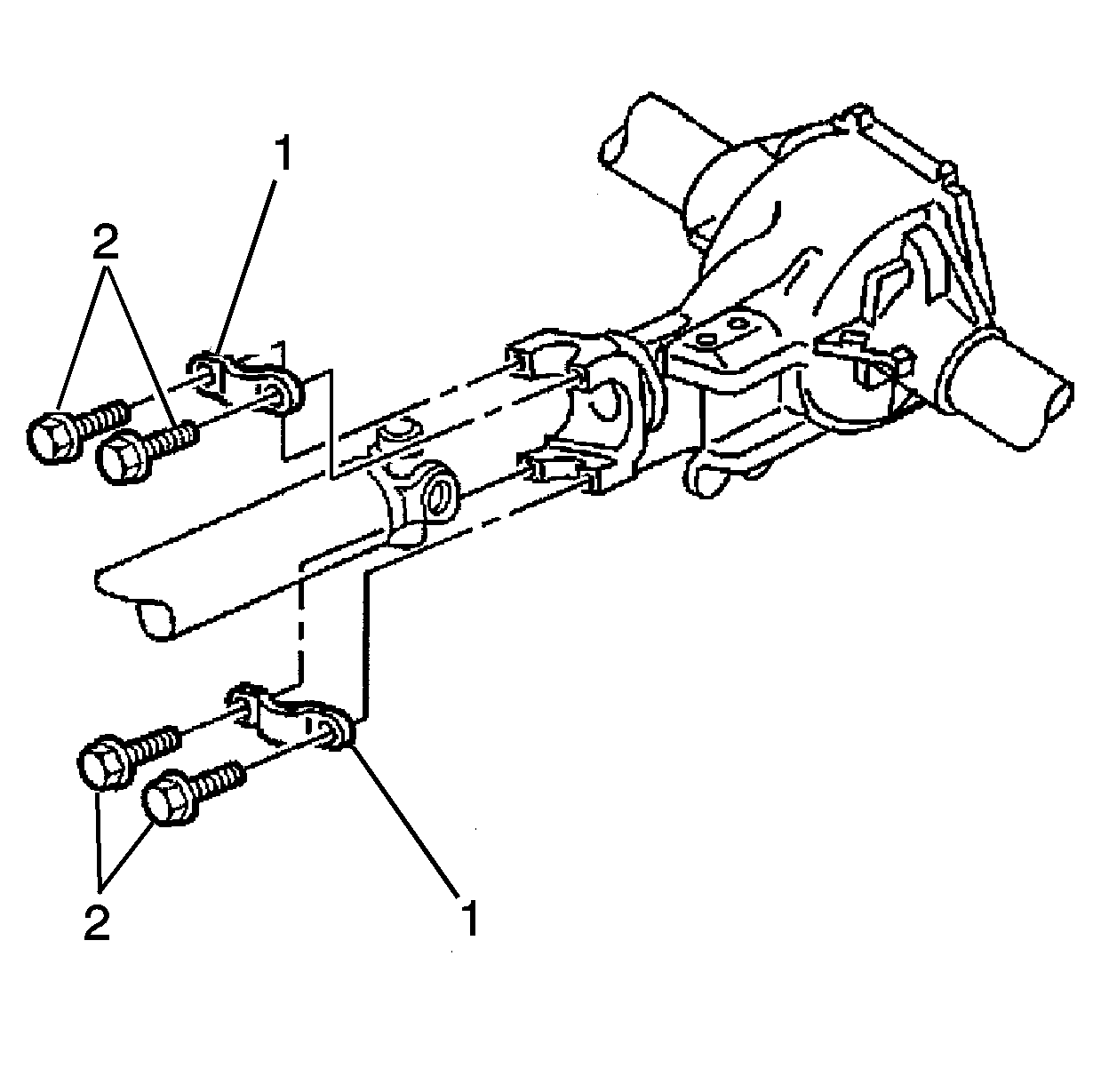
Important: When raising the vehicle, support the vehicle by the frame, allowing the suspension to fully extend (unloaded).
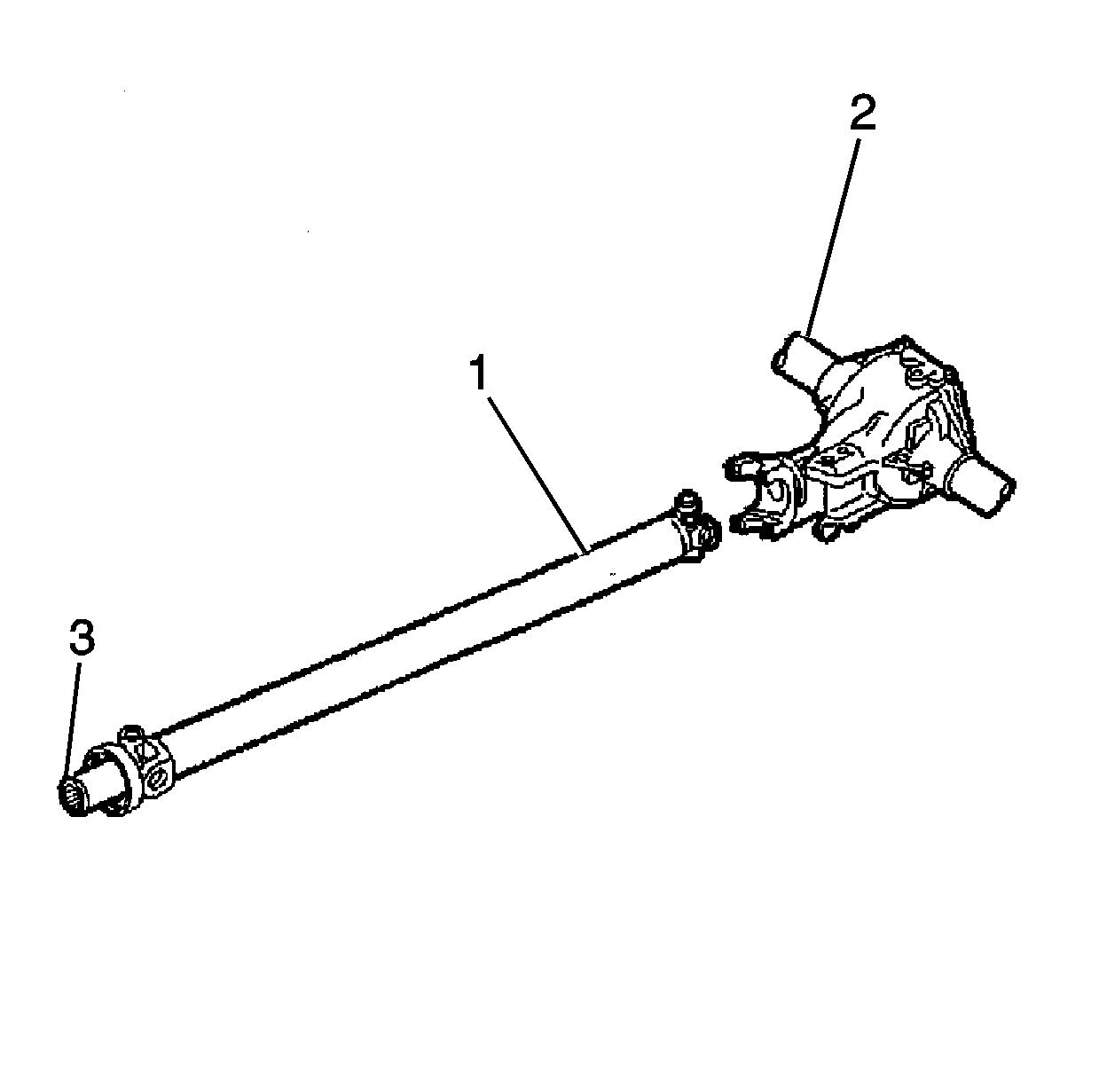
Important: Support the propeller shaft during removal.
| 6.1. | Withdraw the slip yolk (3) from the transmission. |
| 6.2. | Move the propeller shaft (1) rearward and pass the propeller shaft under the housing (2). |
If the bearing caps are loose, tape the bearing caps together in order to prevent dropping and losing the needle roller bearings.
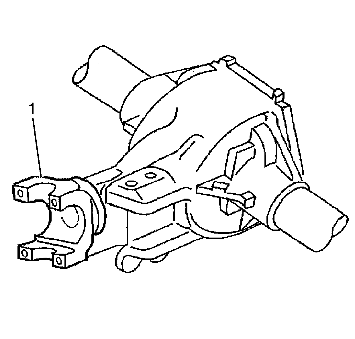
| • | Burrs |
| • | Foreign material |
Torque Arm Removal
- Remove the bolts (2), the washers (3) and the nuts (4) from the rear axle (1).
- Remove the nut (5) from the automatic transmission.
- Remove the outer bracket (8).
- Remove transmission vent tube from torque arm.
- Remove the torque arm (6) and discard.
- Remove bolts and hanger from catalytic converter.
- Suitably support rear of transmission.
- Remove transmission mount nut.
- Remove bolts and transmission support.
- Remove bolts and transmission mount (automatic transmission mount is the same as this available illustration of manual transmission mount).
- Lower transmission.
- Disconnect electrical connectors from vehicle speed sensor and O2 sensor.
- Remove the vehicle speed sensor bolt.
- Remove the vehicle speed sensor.
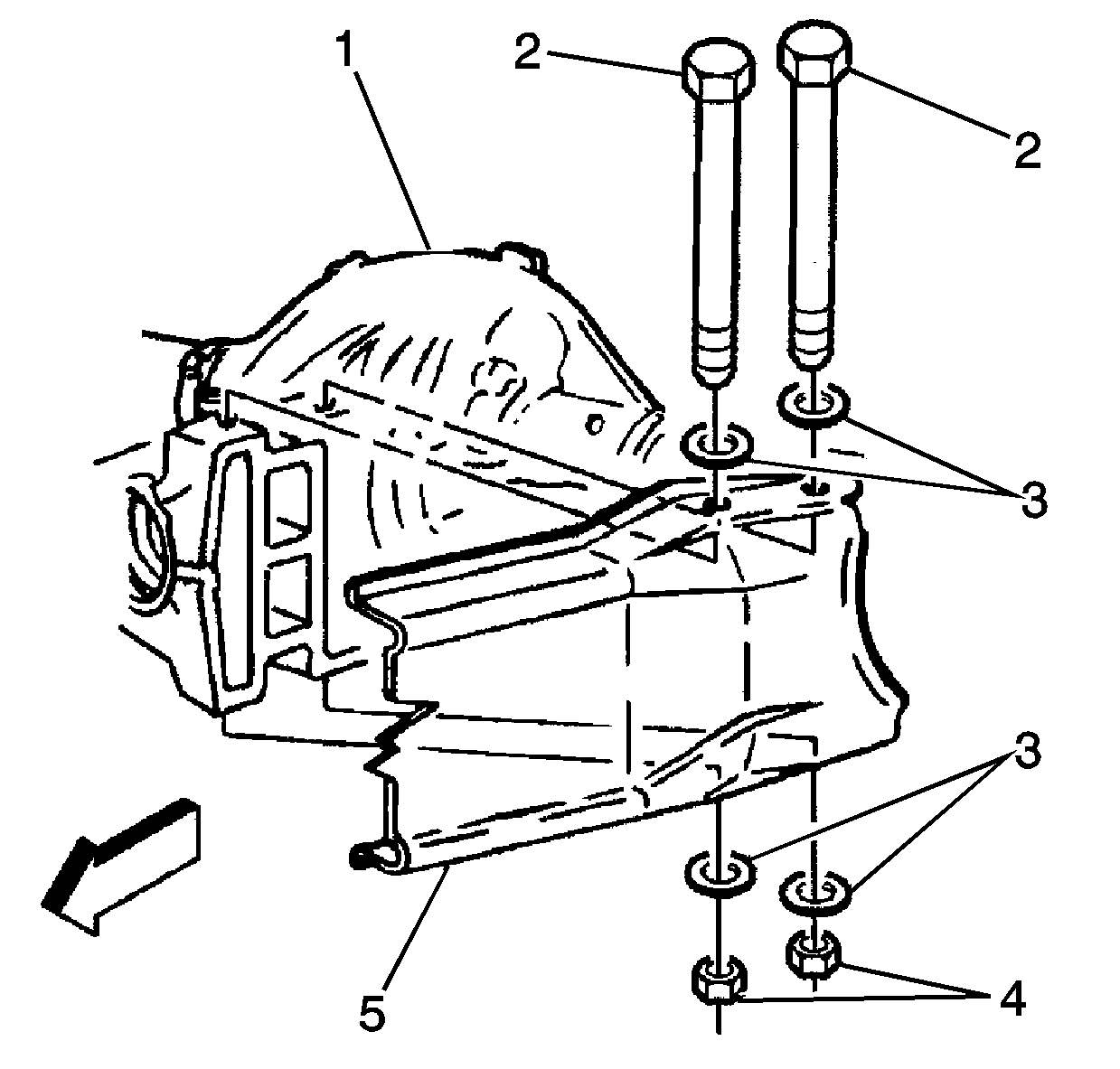
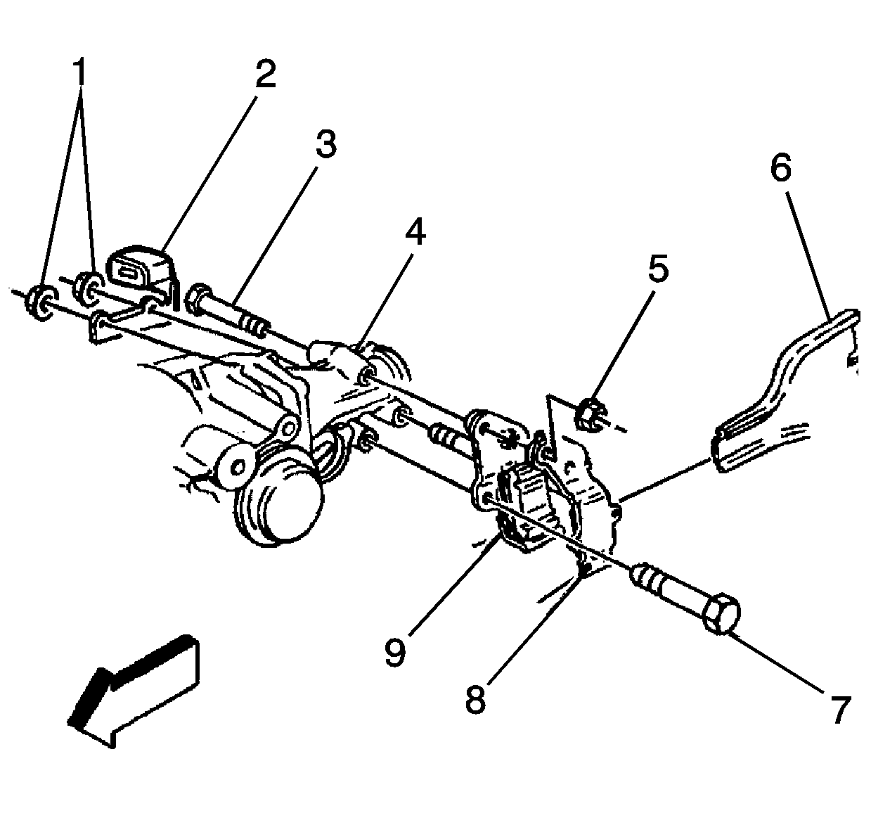
Caution: When the outer bracket (8) is removed, the torque arm (6) may move upward that can result in a pinch point. Avoid placing fingers on top of torque arm.
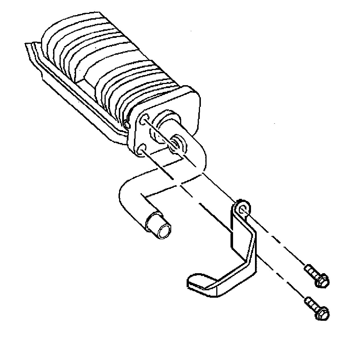
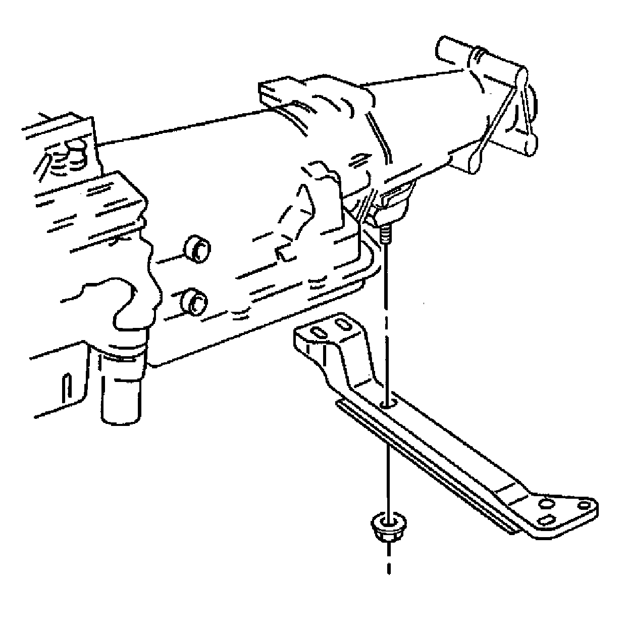
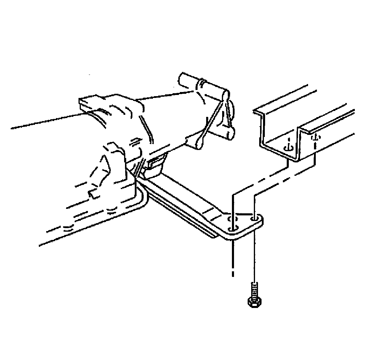
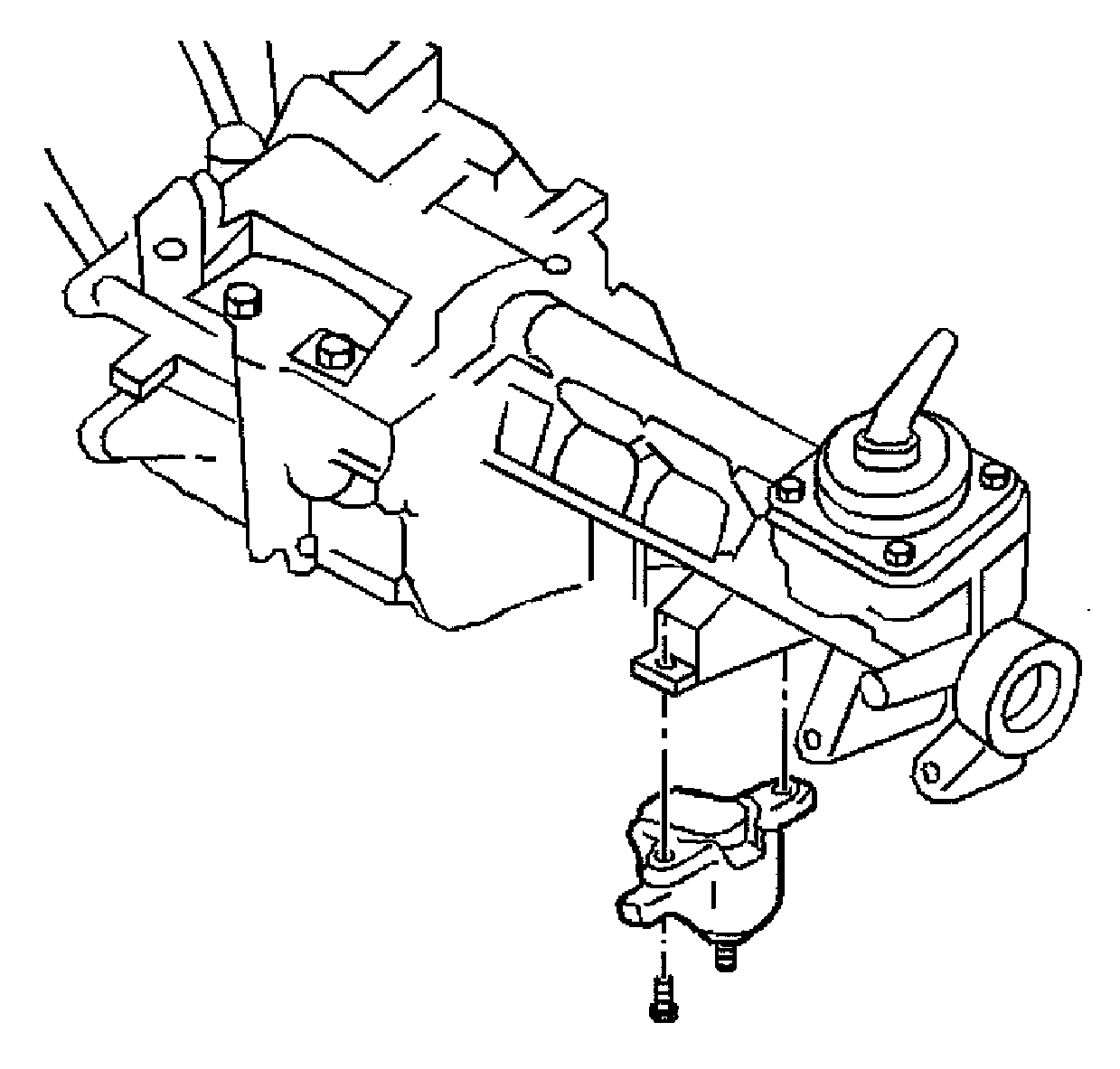
Notice: When lowering transmission, watch for interference with other vehicle components.
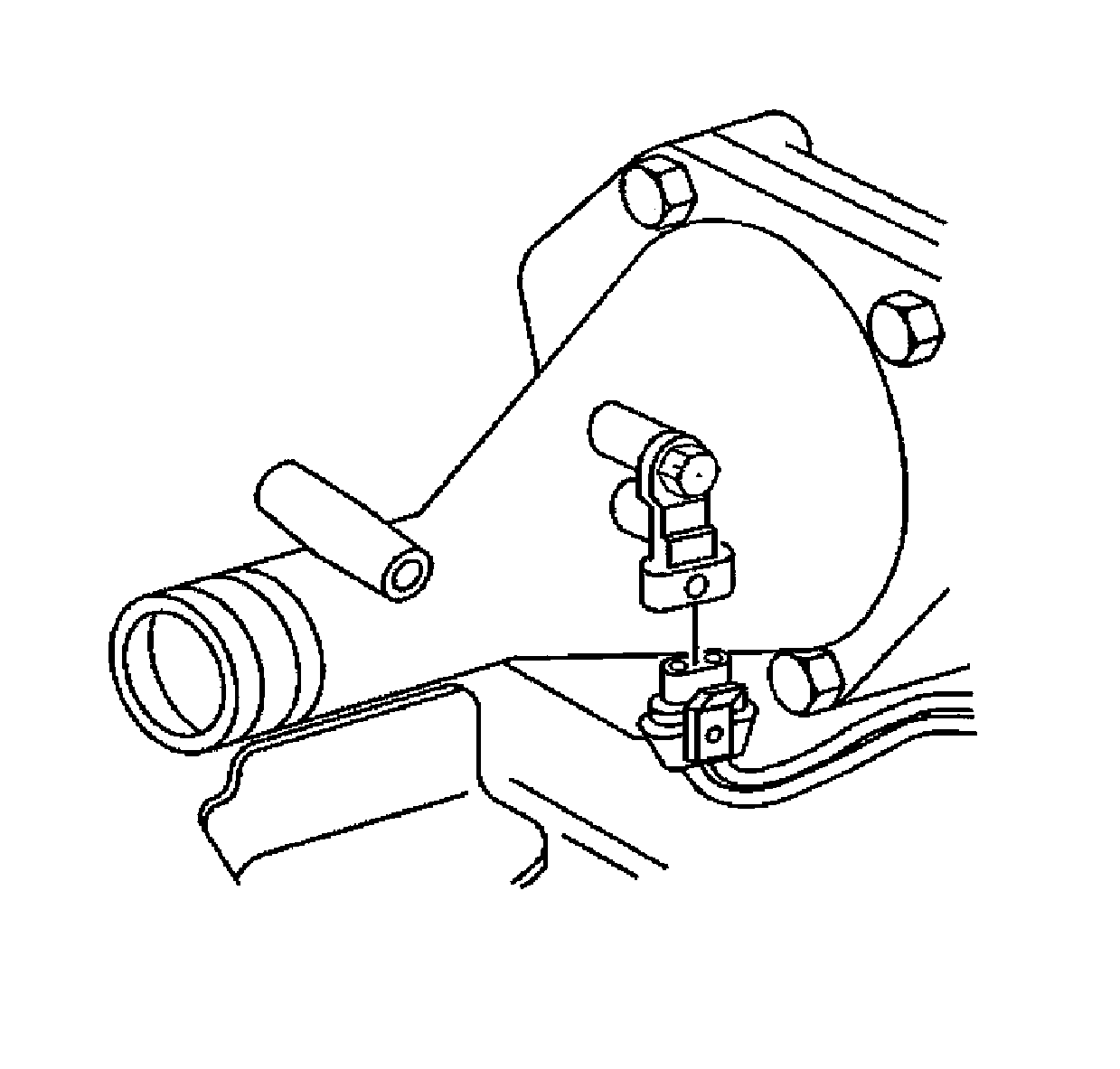
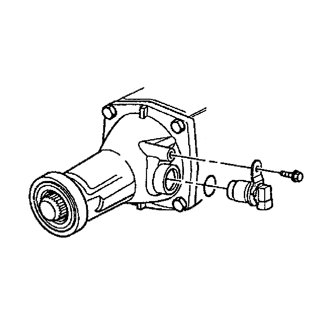
Transmission Case Extension Removal and Inspection
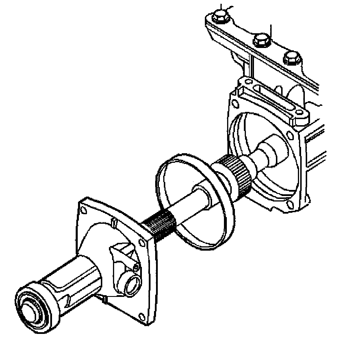
- Remove the case extension bolts.
- Remove the case extension.
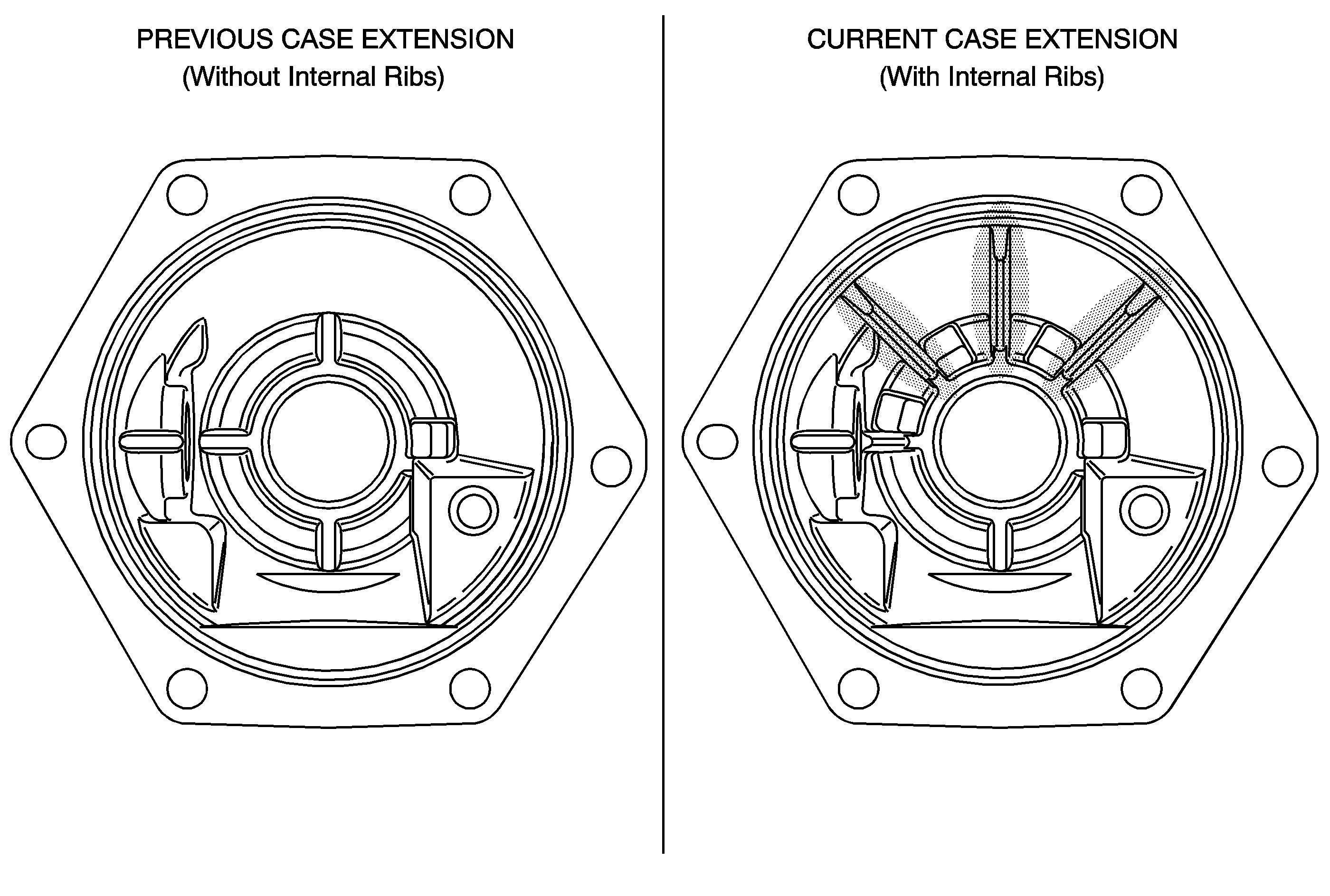
- Inspect the removed case extension to determine if it is the "previous" or "current" design. The "current" design will have the additional internal ribs inside the case extension (reference shaded areas).
- If the removed case extension is the "previous" design, discard the removed case extension and replace with a new "current" design case extension (part no. 24209544, includes case extension oil seal and case extension bushing). Go to step 1 of the Transmission Case Extension Installation Procedure.
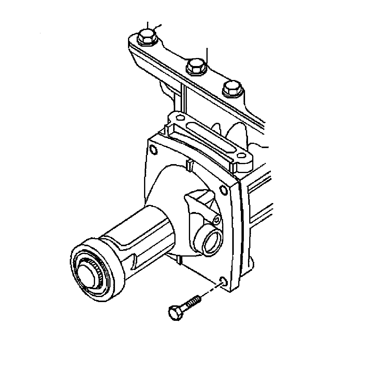
Important: The catalytic converter front hanger and inner bracket (reference items 2 and 9 from step 2 of the Torque Arm Removal Procedure) will remain attached to the case extension at this point.
Disassemble Transmission Case Extension
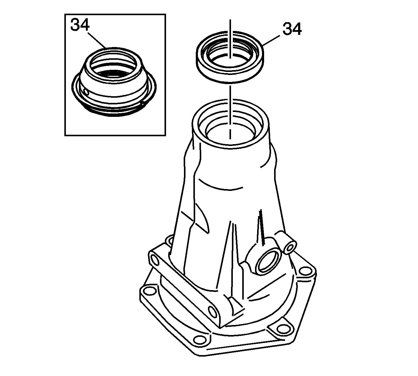
- Remove the case extension (to transmission case) seal. Discard seal.
- Remove the case extension oil seal assembly (34).
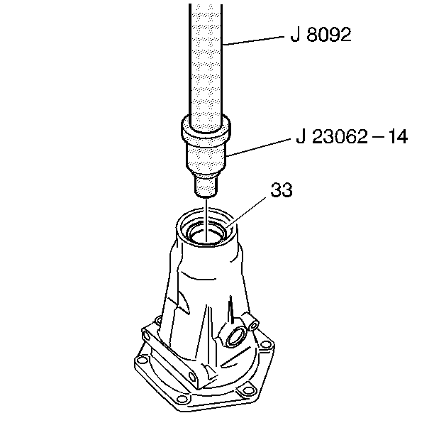
- Using J 23062-14 and J 8092, remove the case extension bushing (33).
Assemble Transmission Case Extension
- Using J 34196-4 and J 8092, install the case extension bushing (33).
- Using J 21426, install the case extension oil seal.
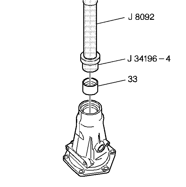
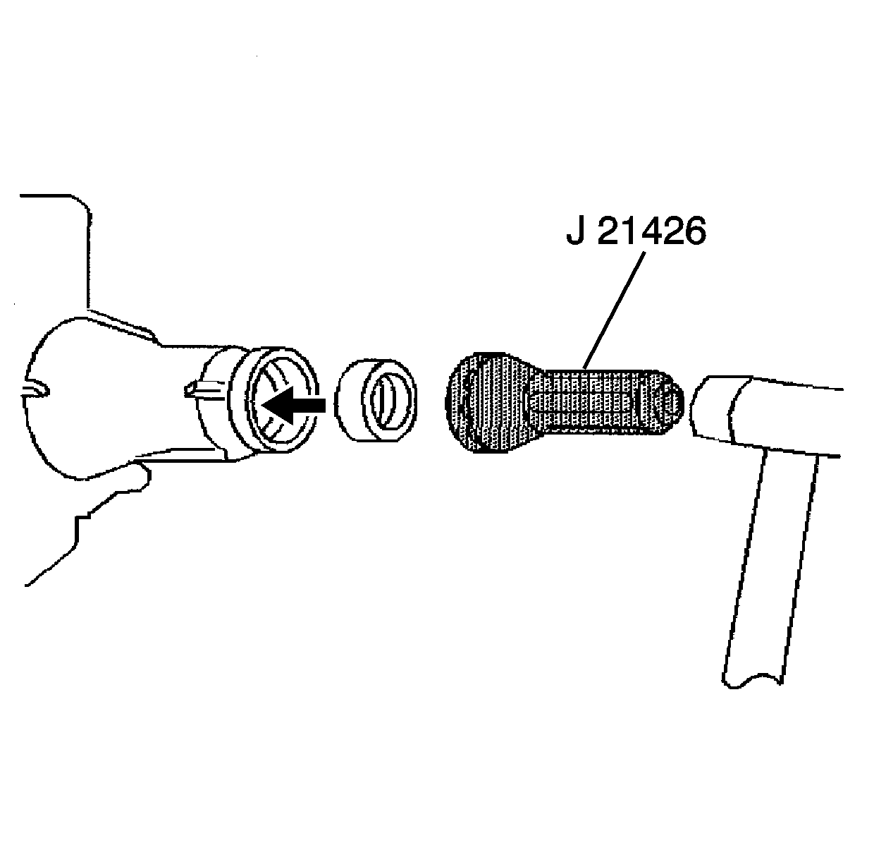
Transfer Parts from "Previous" to "New" Case Extension.
Transmission Case Extension Installation
- Install the new case extension seal to case extension.
- Install the case extension.
- Install the case extension bolts.
- Apply DEXRON III to new vehicle speed sensor O-ring seal.
- Install the new vehicle speed sensor O-ring seal to vehicle speed sensor.
- Install the new vehicle speed sensor.
- Install the vehicle speed sensor bolt.
- Connect electrical connectors to vehicle speed sensor and O2 sensor.
- Raise transmission.
- Install bolts and transmission mount.
- Install bolts and transmission support.
- Remove transmission support jack.
- Install transmission mount nut.
- Install hanger and bolts to catalytic converter.


Notice: Refer to Fastener Notice in Cautions and Notices.
Tighten
Tighten the case extension bolts to 35 N·m (26 lb ft).

Tighten
Tighten the vehicle speed sensor bolt to 11 N·m (97 lb in).


Tighten
Tighten bolts to 48 N·m (36 lb ft).

Tighten
Tighten bolts to 57 N·m (43 lb ft).

Tighten
Tighten nut to 57 N·m (43 lb ft).

Tighten
Tighten bolts to 57 N·m (43 lb ft).
Torque Arm Installation
- Position the new torque arm (5) to the rear axle (1).
- Install the bolts (2), the washers (3) and the nuts (4).
- Position the new torque arm (6) to inner bracket (9).
- Install the outer bracket (8).
- Install the nut (5).
- Install transmission vent tube to torque arm.
- Install bolt, washer, damper and nut to torque arm.

Tighten
Tighten the nuts (4) to 132 N·m (97 lb ft).

Tighten
Tighten the nut (5) to 45 N·m (33 lb ft).
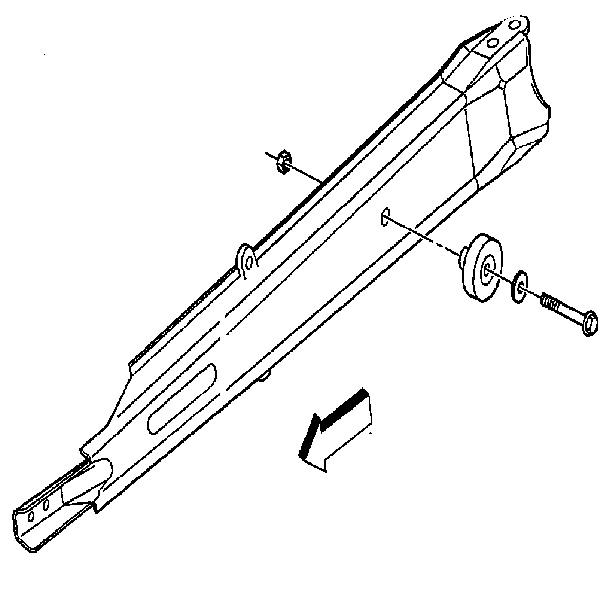
Tighten
Tighten the nut to 50 N·m (37 lb ft).
2-Piece Propeller Shaft Installation
- Remove rear axle support jacks.
- Lubricate the front slip yolk (3) with DEXRON III.
- Install the slip yolk (3) onto the transmission output shaft.
- Install the rear universal joint (2) to the pinion gear yolk (1).
- Install the propeller shaft retainers (1).
- Install the propeller shaft retainer screws (2).
- Install screws (4) to centre support bearing (3), washers (1) and torque arm (2).
- Lower vehicle.
- Place transmission into park.
- Check for leaks and adjust for proper transmission fluid level. Refer to the Automatic Transmission Fluid Checking Procedure section in the Service Manual.
- Install Campaign Identification Label.
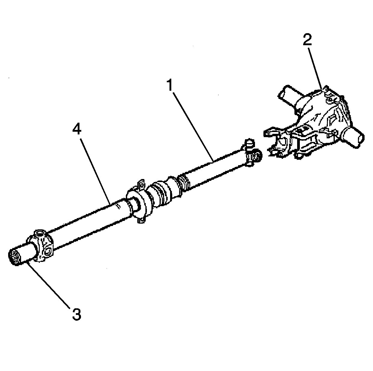
Notice: The propeller shaft must be supported carefully during handling to avoid jamming or bending of parts.
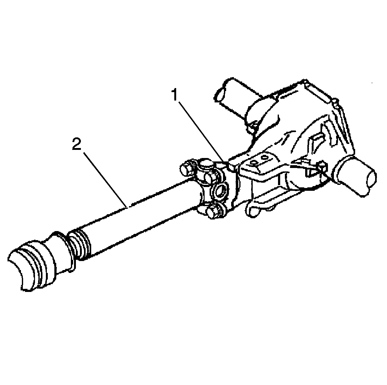
Ensure that the bearing caps are properly seated.

Tighten
Tighten the propeller shaft retainer screws (2) evenly to 22 N·m
(16 lb ft).
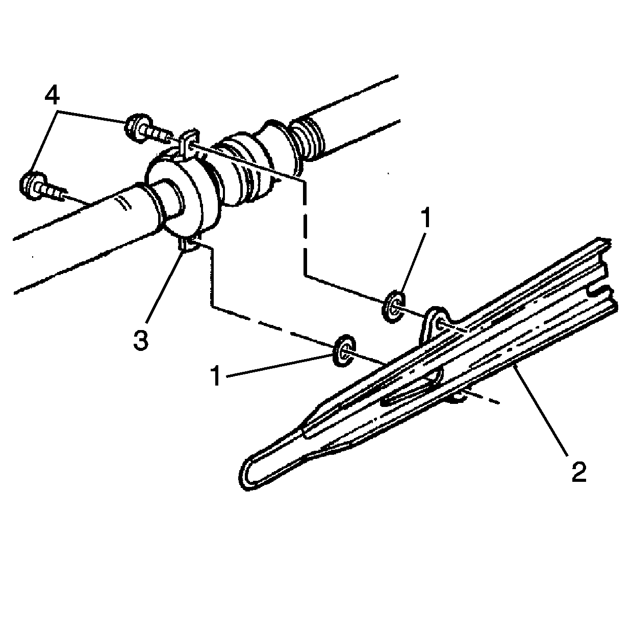
Tighten
Tighten the screws (4) to 50 N·m (37 lb ft).
Campaign Identification Label
Each vehicle corrected in accordance with the instructions outlined in this Product Campaign Bulletin will require a "Campaign Identification Label." Each label provides a space to include the campaign number and the five (5) digit dealer code of the dealer performing the campaign service. This information may be inserted with a typewriter or a ball point pen.

Each "Campaign Identification Label" is to be located on the radiator core support in an area which will be visible when the vehicle is brought in by the customer for periodic servicing. Additional Campaign Identification Labels can be obtained from your Regional Marketing Office.
Apply the "Campaign Identification Label" only on a clean, dry surface.
Claim Information
Submit a Product Campaign Claim with the information indicated below.
Repair Performed | Part Count | Part No. | Parts Allow | CC-FC | Labour Op | Labour Hours* |
|---|---|---|---|---|---|---|
Replace case extension, propshaft and torque arm. | 2 | -- | ** | MA-96 | V0304 | 1.2 |
Recondition case extension; replace propshaft and torque arm. | 1 | -- | ** | MA-96 | V0305 | 1.2 |
* -- For Campaign Administrative Allowance, add 0.1 hours to the "Labour Hours". ** -- The "Parts Allowance" should be the sum total of the current GMSPO Dealer Net price plus landed cost mark-up for parts needed to complete the repair. | ||||||
Refer to the General Motors Claims Processing Manual for details on Product Campaign Claim Submission.
