Intake Manifold Cleaning and Inspection F Car
Cleaning Procedure
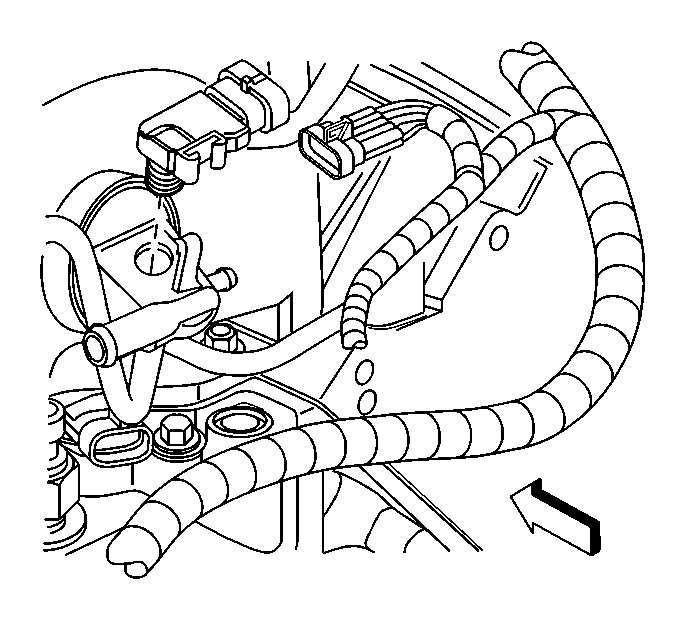
Important: Do not reuse the intake manifold-to-cylinder head sealing gaskets.
- Remove the Manifold Absolute Pressure (MAP) sensor from the rear
of the intake. The MAP sensor is to be reinstalled upon completion of the
cleaning and inspection procedures.
- Inspect the sealing grommet on the MAP sensor. The grommet should
not be torn or damaged.
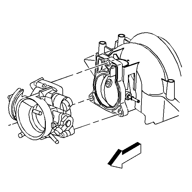
- Remove the throttle body
and bolts.
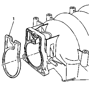
- Remove the throttle body gasket (1).
- Discard the gasket.
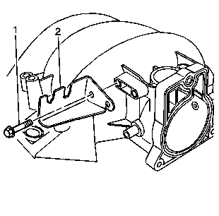
- Remove the accelerator control cable bracket (2) and bolts (1),
if required.
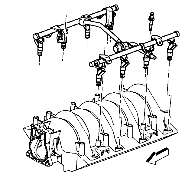
- Remove the fuel rail with
injectors.
Refer to
Fuel Rail and Injectors Removal
.
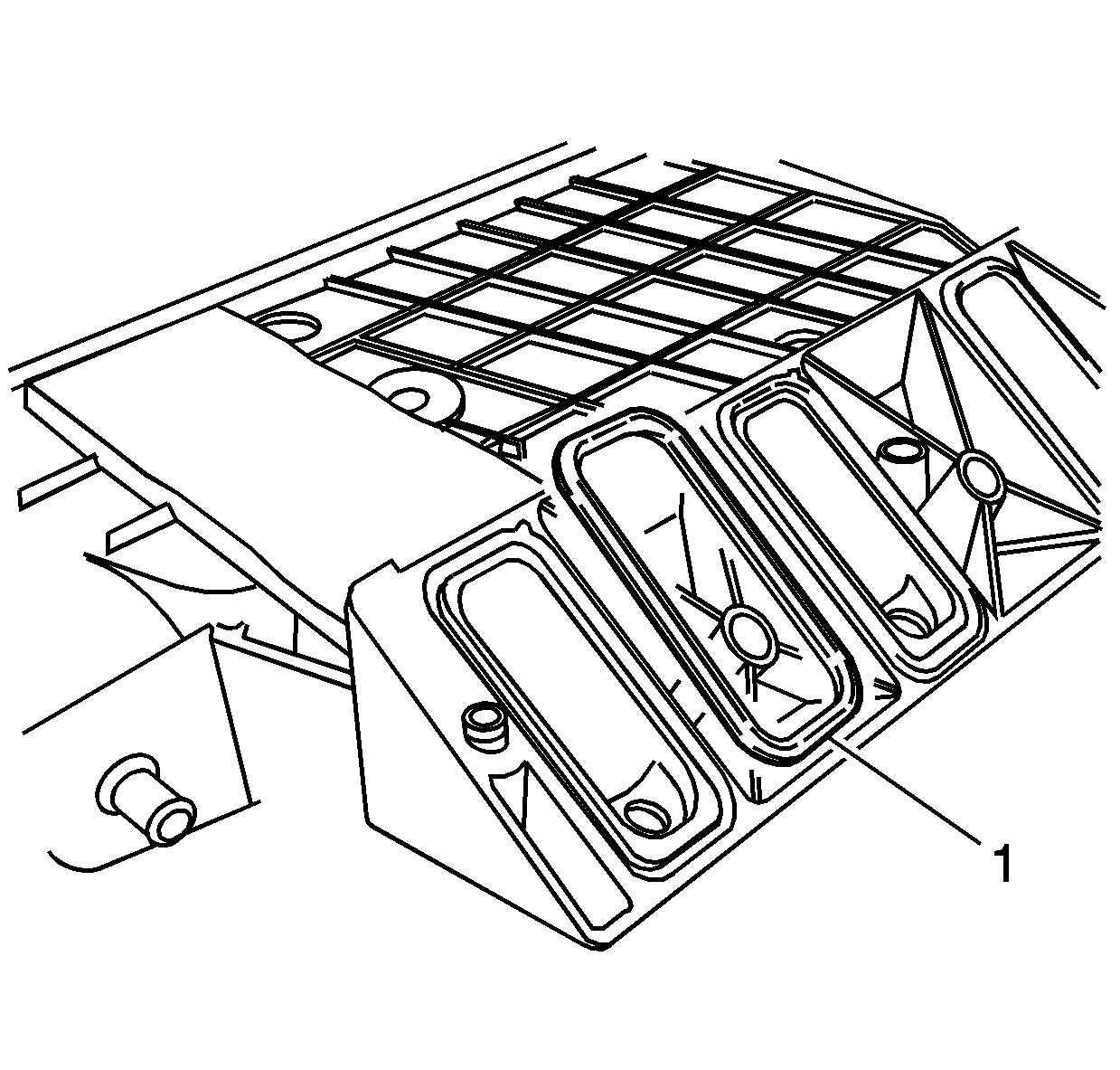
- Remove and discard the intake manifold-to-cylinder head gaskets (1).
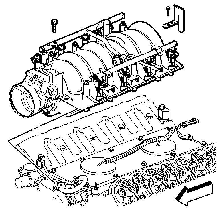
- Clean the intake manifold
in solvent.
| • | Clean the intake manifold gasket grooves. |
| • | Clean the intake manifold vacuum passages at the rear of the intake. |
Caution: Wear safety glasses in order to avoid eye damage.
- Dry the intake manifold with compressed air.
- Upon installation of the intake manifold, install NEW manifold-to-cylinder
head gaskets.
Inspection Procedure

- Inspect the throttle body
bolt inserts for looseness or damaged threads.

- Inspect the fuel rail
bolt inserts for looseness or damaged threads.
- Inspect the intake manifold vacuum passages for debris or restrictions.

Important: The rear Manifold Absolute Pressure (MAP) sensor housing is retained
to the intake manifold by push-in-place snap lock design.
The rear MAP sensor housing is sealed at the intake manifold by an O-ring
seal.
- Inspect the rear MAP sensor housing.
| • | Inspect for damaged or broken vacuum fittings, damaged MAP sensor
mounting bore, or broken MAP sensor retaining tab. |
| • | Inspect the rear MAP sensor housing for looseness or poor sealing
to the intake manifold. Repair or replace the components as necessary. |
- Inspect the composite intake manifold assembly for cracks or damage.
Inspect the areas between the intake runners.
- Inspect all the gasket sealing surfaces and grooves for cracking
or damage.

- Inspect the fuel injector
bores for excessive scoring or damage.
- Inspect the intake manifold cylinder head deck for warpage.
| 8.1. | Locate a straight edge across the intake manifold cylinder head
deck surface. |
| 8.2. | Insert a feeler gauge between the intake manifold and the straight
edge. |
A intake manifold with warpage in excess of 0.5 mm
(0.02 in), must be replaced.
- Upon completion of inspection, install the MAP sensor to the manifold.
Intake Manifold Cleaning and Inspection Y Car
Cleaning Procedure

- Remove the Manifold Absolute Pressure (MAP) sensor from the
rear of the intake manifold. The MAP sensor is to be reinstalled upon completion
of the cleaning and inspection procedures.
- Inspect the sealing grommet on the MAP sensor. The grommet should
not be torn or damaged.
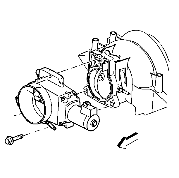
- Remove the throttle body.

- Remove the throttle body gasket (1).
- Discard the gasket.

- Remove the fuel rail with
injectors.

- Remove and discard the intake manifold-to-cylinder head gaskets (1).
- Clean the intake manifold in solvent.
| • | Clean the intake manifold gasket grooves. |
| • | Clean the intake manifold vacuum passages at the rear of the intake. |
Caution: Wear safety glasses in order to avoid eye damage.
- Dry the intake manifold with compressed air.
- Upon installation of the intake manifold, install NEW manifold-to-cylinder
head gaskets.
Inspection Procedure

- Inspect the throttle body
bolt inserts for looseness or damaged threads.

- Inspect the fuel rail
bolt inserts for looseness or damaged threads.
- Inspect the intake manifold vacuum passages for debris or restrictions.

Important: The rear Manifold Absolute Pressure (MAP) sensor housing is retained
to the intake manifold by push-in-place snap lock design.
The rear MAP sensor housing is sealed at the intake manifold by an O-ring
seal.
- Inspect the rear MAP sensor housing.
| • | Inspect for damaged or broken vacuum fittings, damaged MAP sensor
mounting bore, or broken MAP sensor retaining tab. |
| • | Inspect the rear MAP sensor housing for looseness or poor sealing
to the intake manifold. Repair or replace the components as necessary. |
- Inspect the composite intake manifold assembly for cracks or damage.
Inspect the areas between the intake runners.
- Inspect all the gasket sealing surfaces and grooves for cracking
or damage.

- Inspect the fuel injector
bores for excessive scoring or damage.
- Inspect the intake manifold cylinder head deck for warpage.
| 8.1. | Locate a straight edge across the intake manifold cylinder head
deck surface. |
| 8.2. | Insert a feeler gauge between the intake manifold and the straight
edge. |
A intake manifold with warpage in excess of 0.5 mm
(0.02 in), must be replaced.
- Upon completion of inspection, install the MAP sensor to the manifold.


