Mode Valve Actuator Replacement Lower
Removal Procedure
- Remove the instrument panel (IP) carrier. Refer to Instrument Panel Carrier Replacement in Instrument Panel, Gages, and Console.
- Remove the front floor air duct. Refer to Floor Air Outlet Replacement .
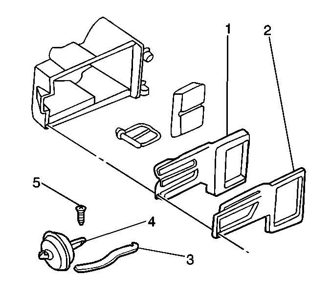
- Remove the air distributor case face (1) and seal (2).
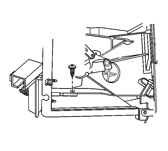
- Remove the mode actuator screw (5).
- Disconnect the mode actuator linkage (3) from the mode door by twisting and pulling upward.
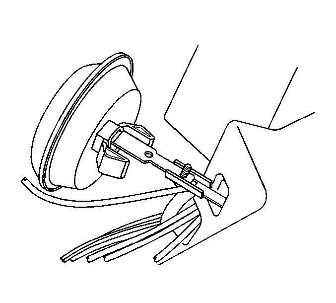
- Compress the actuator tabs and remove the mode actuator (4) and linkage (3).
- Disconnect the vacuum line from the actuator.

Installation Procedure
- Connect the vacuum line to the actuator.
- Install the mode actuator (4) and linkage (3).
- Install the mode actuator screw (5).
- Install the air distributor case face (1) and seal (2).
- Install the front floor air duct. Refer to Floor Air Outlet Replacement .
- Install the IP carrier. Refer to Instrument Panel Carrier Replacement in Instrument Panel, Gages and Console.

Notice: Refer to Fastener Notice in the Preface section.
Tighten
Tighten the mode actuator screw to 2 N·m (18 lb in).
Mode Valve Actuator Replacement Upper
Removal Procedure
- Remove the instrument panel (IP) carrier. Refer to Instrument Panel Carrier Replacement in Instrument Panel, Gages and Console.
- Remove the front floor air duct. Refer to Floor Air Outlet Replacement .
- Remove the air distributor case face and seal.
- Remove the linkage screw holding the lower mode door to the actuator.
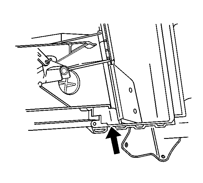
- Remove the mode door from the holding bracket in order to gain acess to the upper mode actuator screw.
- Compress the actuator tabs from inside the HVAC module assembly and remove the upper mode actuator and linkage.
- Remove the upper mode actuator screw.
- Disconnect the vacuum line from the actuator.


Installation Procedure
- Connect the vacuum line.
- Install the upper mode actuator screw (5).
- Install the actuator to the HVAC module assembly. Push the tabs inward until an audible click is heard.
- Install the lower mode actuator screw and linkage.
- Reinstall the mode door into the retaining bracket.
- Install the air distributor case face and seal.
- Remove the front floor air duct. Refer to Floor Air Outlet Replacement .
- Remove the instrument panel (IP) carrier. Refer to Instrument Panel Carrier Replacement in Instrument Panel, Gages and Console.
Notice: Use the correct fastener in the correct location. Replacement fasteners must be the correct part number for that application. Fasteners requiring replacement or fasteners requiring the use of thread locking compound or sealant are identified in the service procedure. Do not use paints, lubricants, or corrosion inhibitors on fasteners or fastener joint surfaces unless specified. These coatings affect fastener torque and joint clamping force and may damage the fastener. Use the correct tightening sequence and specifications when installing fasteners in order to avoid damage to parts and systems.
Tighten
Tighten the mode actuator screw to 2 N·m (18 lb in).


Tighten
Tighten the mode actuator screw to 2 N·m (18 lb in).

Verify the operation of the mode door making sure it is sealing properly.
