Front Wheelhouse Replacement Panel Upper Side Rail
When replacing the upper side rail assembly, cut a section of the damaged side rail assembly away and section a new side rail assembly in its place. Removal of the side rail assembly requires the use of a template to help in determining the location of the cut to be made.
Removal Procedure
- Remove the outer side rail. Refer to Side Rail Replacement
- Position template included with rail to side rail assembly at forward edge where indicated by arrows and scribe line onto side rail assembly.
- Drill out the welds at cowl panel. The remaining welds will hold side rail assembly in place while cutting.
- Separate side rail assembly away from cowl panel.
- Cut the side rail assembly at scribed lines, being careful not to cut adjacent panels.
- Drill out the remaining welds (1).
- Remove the side rail assembly.
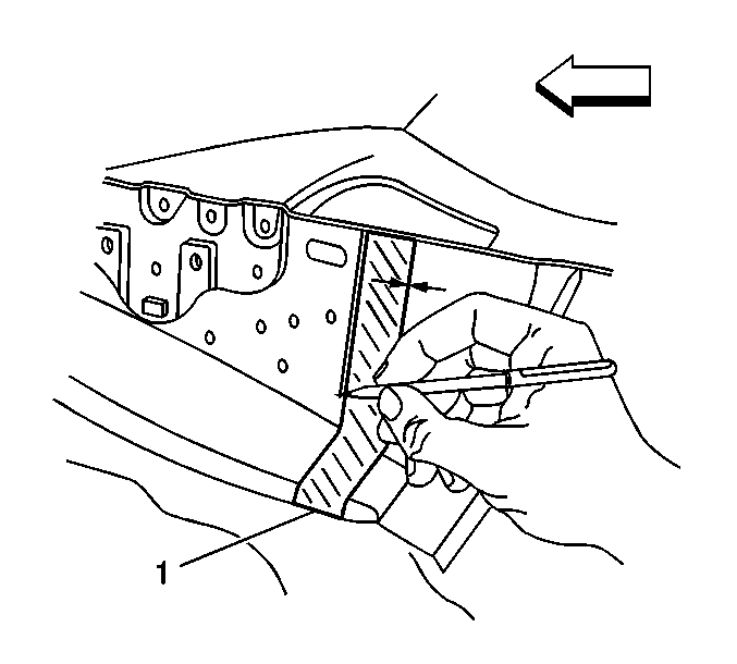
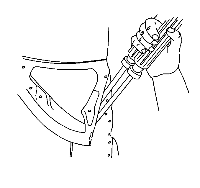
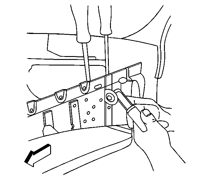
Important: Note the number and the location of remaining welds for installation of new side rail assembly.
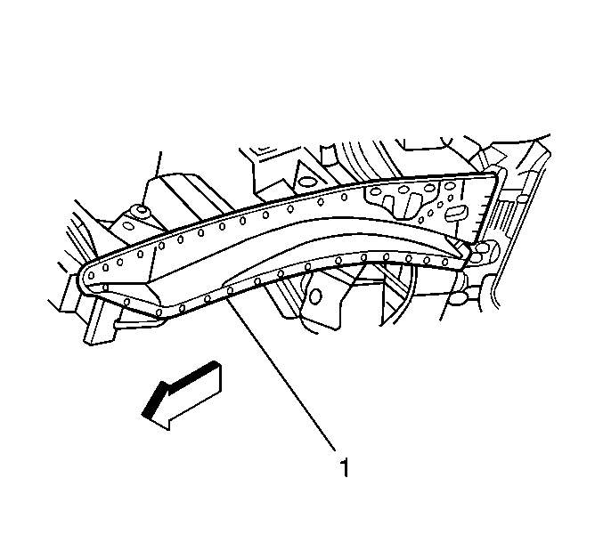
Installation Procedure
- Prepare mating surfaces for proper fit of new side rail assembly.
- Clean sealer away from mating surfaces as necessary.
- On new side assembly drill 8 mm (5/16 in) holes along mating surfaces as noted from original side rail assembly.
- Clean the surface of 7 pierced locations on side rail assembly with mild soap and water.
- Wipe dry.
- Clean with wax and grease remover.
- Remove backing from washers included with rail and carefully apply to motor compartment side of new side rail assembly at pierced locations.
- Position new side rail assembly to overlap remainder of original side rail assembly by 35 mm. Align to arrows on remainder of original side rail assembly and clamp.
- Using a MIG welder, at overlap, plug weld all 8 mm pre-drilled holes in new side rail assembly in sequence shown.
- Using a MIG welder, randomly plug weld all remaining holes (1-9) in new side rail assembly.
- Complete stitch welding along seam.
- Remove the clamps.
- Clean and prepare welded surfaces.
- Prime with 2-part catalyzed primer.
- Install outer side rail.
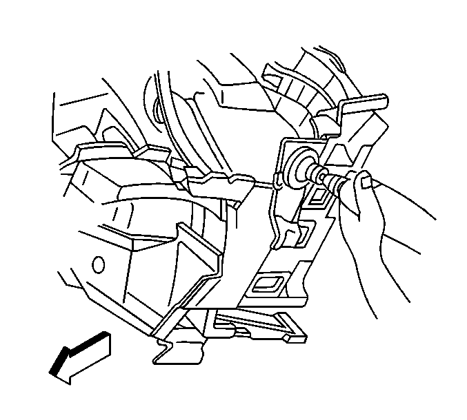
Important: If original side rail assembly is damaged beyond recognition, place holes for welding 1 1/2 in apart.
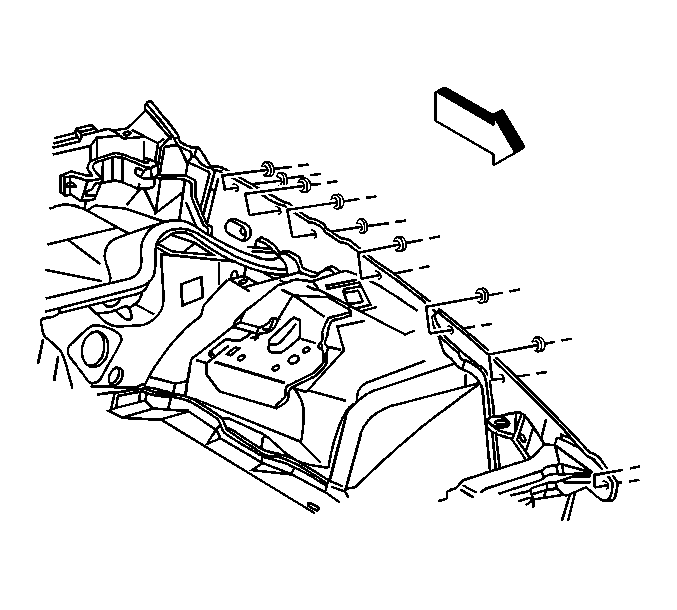
Important: Use only service kit washers provided with rail, GM P/N 12520407. Use of any other washer could cause improper positioning of side rail assembly.
Important: The forward pierced location may need to be manually positioned according to upper body dimensions, utilizing common tools and techniques.
Important: Be sure to measure continually throughout welding process to maintain correct dimensions.
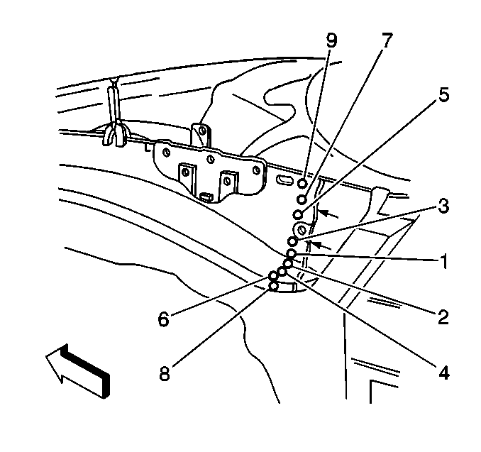
Important: Prior to refinishing, refer to GM 4901MD-99 Refinish Manual for recommended products. Do not combine paint systems. Refer to paint manufacturer' s recommendations
Front Wheelhouse Replacement Complete
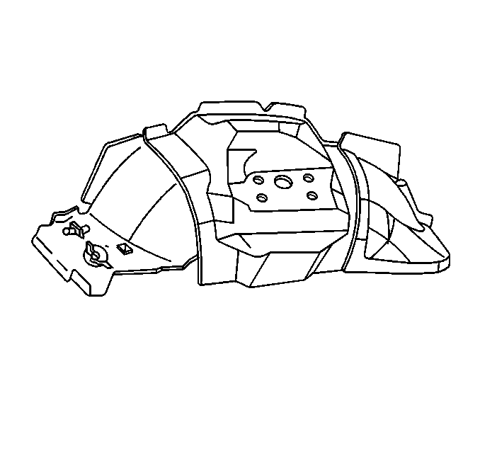
The Front Wheelhouse is available as an entire assembly, including all brackets, reinforcements and drill template.
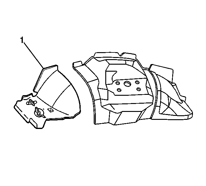
The Front Wheelhouse Apron is also available separately (1).
Removal Procedure
- Remove all related panels and components.
- Visually inspect the damaged area.
- Restore as much of the damage as possible to factory specifications.
- Remove sealers and anti-corrosion materials as necessary.
- Mark all factory welds.
- Drill out all factory welds.
- Remove the damaged wheelhouse.
- Prepare mating surfaces for proper fit of new front wheelhouse assembly.
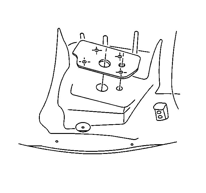
Important: Note the number and location of welds for installation of the front wheelhouse assembly.
Installation Procedure
- Set the new front wheelhouse assembly on a work surface with underside up.
- Position the template (included in service kit) in the front wheelhouse assembly.
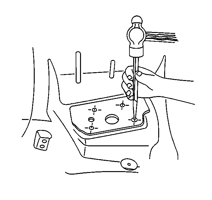
- With a center punch, locate four strut attaching holes.
- Remove template.
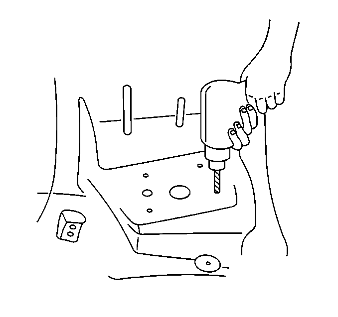
- Drill 12 mm (15/32 in) holes in marked locations on new front wheelhouse assembly.
- Drill 8 mm (5/16 in) plug weld holes along mating surfaces 1 1/2 in apart.
- Position new front wheelhouse assembly in place, align and clamp.
- Using a MIG welder, randomly plug weld the new front wheelhouse assembly in place.
- Remove the clamps.
- Clean and prepare the welded surfaces.
- Apply 3M Brushable Seam Sealer part number 08361 or equivalent as necessary.
- Apply anti-corrosion materials as necessary.
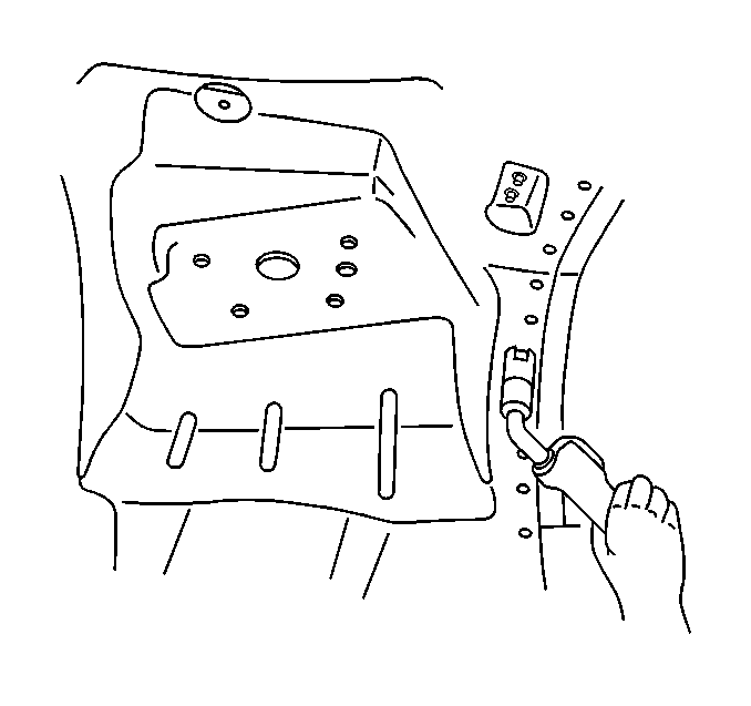
Important: Be sure to measure continually throughout welding process to maintain correct dimensions.
Important: Prior to refinishing, refer to GM 4901MD-99 Refinish Manual for recommended products. Do not combine paint systems. Refer to paint manufacturer's recommendatiosn.
