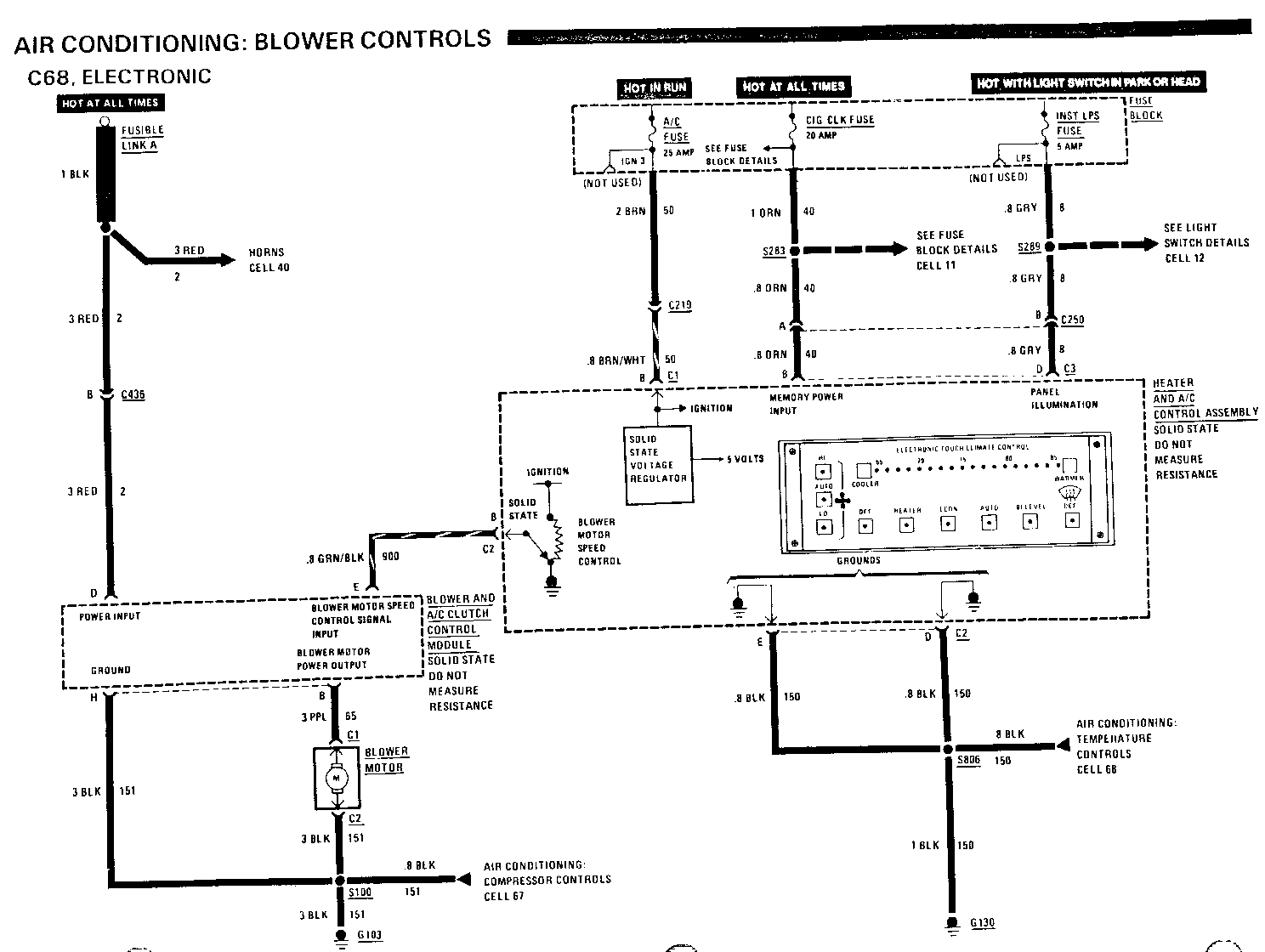
MANUAL UPDATE-SECTION 8A A/C BLOWER CONTROLS C68

VEHICLES AFFECTED: 1989 BUICK B-CAR
Update pages 8A 66-0, 2, 67-1,4 and 202-8 to reflect the change to the Delco Electronics Power Interface Module for the C68 system.
(corrected pages (5) attached)
Cl (PPL) & C See 2 (BLK)
If both voltages are correct but the blower does not run, install a new Blower Motor.
1. Check the PPL (65) wire for an open. If wire is good, do Test B.
2. Check the BLK (151) wire for an open and that ground G 103 is clean and tight.
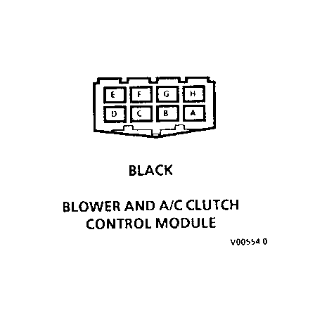
B: BLOWER AND A/C CLUTCH CONTROL MODULE VOLTAGE TEST Measure: VOLTAGE
At: BLOWER AND A/C CLUTCH CONTROL MODULE CONNECTORS (Connected) Conditions: Ignition Switch: RUN A/C Mode: ECON Blower Mode: Hi
Measure Correct For Diagnosis Between Voltage ------- ------- ------------- C1/D(RED) & Battery See 1 Ground C1/E (LT Greater than GRN/BLK)& 10 Volts (use See 2 Ground analog voltmeter) C1/D(RED) & Battery See 3 C2/H (BLK) C2/B (PPL) & Greater than See 5 GROUND 10 volts
Blower Mode: LO
C1/E (LT Less than 7 See 4 GRN/BLK) & Volts (use Ground analog voltmeter)
C2/B (PPL)& Less than 7 See 5 Ground Volts
If all voltages are correct but blower speed does not change when Mode is changed from HI to LO, replace the Heater and A/C Control Assembly.
1. Check RED (2) wire and Fusible Link A for an open.
2. Check LT GRN/BLK (900) wire for an open or short to ground. If wire is good, do Test C.
3. Check BLK (151) wire for an open.
4. Do Test C.
5. Replace Blower and A/C Clutch Control Module.
C: HEATER AND A/C CONTROL ASSEMBLY VOLTAGE TEST
Measure: VOLTAGE
At: HEATER AND A/C CONTROL ASSEMBLY CONNECTORS (Connected)
Conditions:
Ignition Switch: RUN A/C Mode: ECON Blower Mode: HI
Measure Correct For Diagnosis Between Voltage ------- ------- --------------
C1/B (BRN/ WHT) & Battery See 1 Ground
C3/B (ORN & Battery See 2 Ground
C1/B (BRN/ WHT) & C2/E Battery See 3 (BLK)
C1/B (BRN/ WHT) & C2/D Battery See 3 (BLK)
C2/B (LT Greater than GRN/BLK)& 10 Volts (use See 4 Ground analog voltmeter)
Blower Mode: LO
C2/B (LT Less than 7 GRN/BLK) & Volts (use See 4 Ground analog voltmeter)
If all voltages are correct, but blower does not run, check for an open in the LT GRN/BLK (900) wire and re-do Tests A and B.
1. Check BRN/WHT and BRN (50) wires for an open.
AIR CONDITIONING: BLOWER CONTROLS
C68, ELECTRONIC
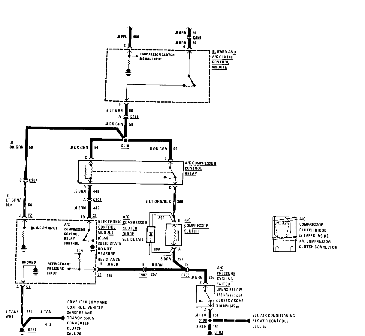
A: ECM COMPRESSOR CONTROL TEST (TABLE 2)
Measure: RESISTANCE
At: ECM CONNECTOR C1 (Disconnected)
Conditions:
Ignition Switch: OFF Negative Battery Terminal: DISCONNECTED
Measure Correct For Diagnosis Between Resistance ------- ---------- -------------- 15 (BLK) & 0 ohms See 1 Ground
If result is correct, go to Table 3.
1. Checkthe BLK(152)andBRN(257)wires for an open.
A: ECM COMPRESSOR CONTROL TEST (TABLE 3)
Connect: FUSED JUMPER At: ECM CONNECTOR C 1 (Disconnected) Conditions:
Ignition Switch:
RUN A/C Mode: AUTO Temperature Setting: 65 Deg F Temperature Outside Car: Above 60 DEG F (16 DEG C)
Jumper Correct Result For Diagnosis Between ------- -------------- -------------- A/C Compressor 19 (BRN) & Control Relay Ground operates and See 1 engages Compressor Clutch
If result is correct, but A/C System does not operate, condition is in ECM. Refer to Section 6E for ECM diagnostic procedures.
1. Replace A/C Compressor Control Relay.
B: A/C COMPRESSOR CLUTCH TEST
Measure: VOLTAGE At: A/C COMPRESSOR CLUTCH CONNECTOR (Disconnected) Conditions: Ignition Switch: RUN (Engine not running) A/C Mode: AUTO Temperature Setting : 65 DEG F Temperature Outside Car: Above 60 DEG F (16 DEG C) A/C Compressor Control Relay: DISCONNECTED A/C Compressor Control Relay terminals B and D jumpered
Measure Correct For Diagnosis Between Voltage ------- ------- -------------- B(LT GRN/ BLK) & Battery See 1 Ground B(LT GRN/ BLK) & A Battery See 2 (BRN)
If both voltages are correct, but Clutch does not engage, replace the Compressor Clutch.
1. Check for an open in LT GRN/BLK (366) wire
2. Check for an open in the BRN (257) wire and BLK (151) wire to ground. A/C Pressure Cycling Switch should be closed. If AC Pressure Cycling Switch is open, check for low refrigerant charge according to procedures in Section 1B. If refrigerant charge is normal, replace the A/C Pressure Cycling Switch.
C: BLOWER AND A/C CLUTCH CONTROL MODULE CLUTCH VOLTAGE TEST
Measure: VOLTAGE
At: BLOWER AND A/C CLUTCH CONTROL MODULE CONNECTOR (Connected) Conditions: Ignition Switch: RUN A/C Mode: AUTO TempeTature Setting: 65 DEG F Temperature Outside Car: Above 60 DEG F (16DEG C)
Measure Correct For Diagnosis Between Voltage ------- ------- -------------- C1/A (BRN)& Battery See 1 Ground
C1/C (PPL) & 5 to 7 volts See 2 Ground
C1/F (LT GRN) & Battery See 3 Ground
A/C Mode: ECON
C1/C (PPL) & Battery See 2 Ground
C1/F(LT GRN) & Less Than 1 See 3 Ground Volt
General Motors bulletins are intended for use by professional technicians, not a "do-it-yourselfer". They are written to inform those technicians of conditions that may occur on some vehicles, or to provide information that could assist in the proper service of a vehicle. Properly trained technicians have the equipment, tools, safety instructions and know-how to do a job properly and safely. If a condition is described, do not assume that the bulletin applies to your vehicle, or that your vehicle will have that condition. See a General Motors dealer servicing your brand of General Motors vehicle for information on whether your vehicle may benefit from the information.
