SERVICE MANUAL UPDATE SEC. 8A REV. KEYLESS ENTRY MODULE

Subject: KEYLESS ENTRY MODULE REVISED
Model and Year: 1992 CAPRICE
Some early 1992 Caprice Sedans were built with a one connector keyless entry receiver module and shipped without transmitters. These vehicles were not intended to provide the keyless entry feature for the customers use. These receiver modules must be in the vehicle for normal operation of the driver's door power door lock actuator to function. If dealers program a transmitter to activate the keyless entry feature, the deck lid release will not operate.
The 1992 Caprice Sedan/Wagon Service Manual can be utilized for the driver's door lock actuator diagnosis and repair when working on a vehicle with a one connector keyless entry module.
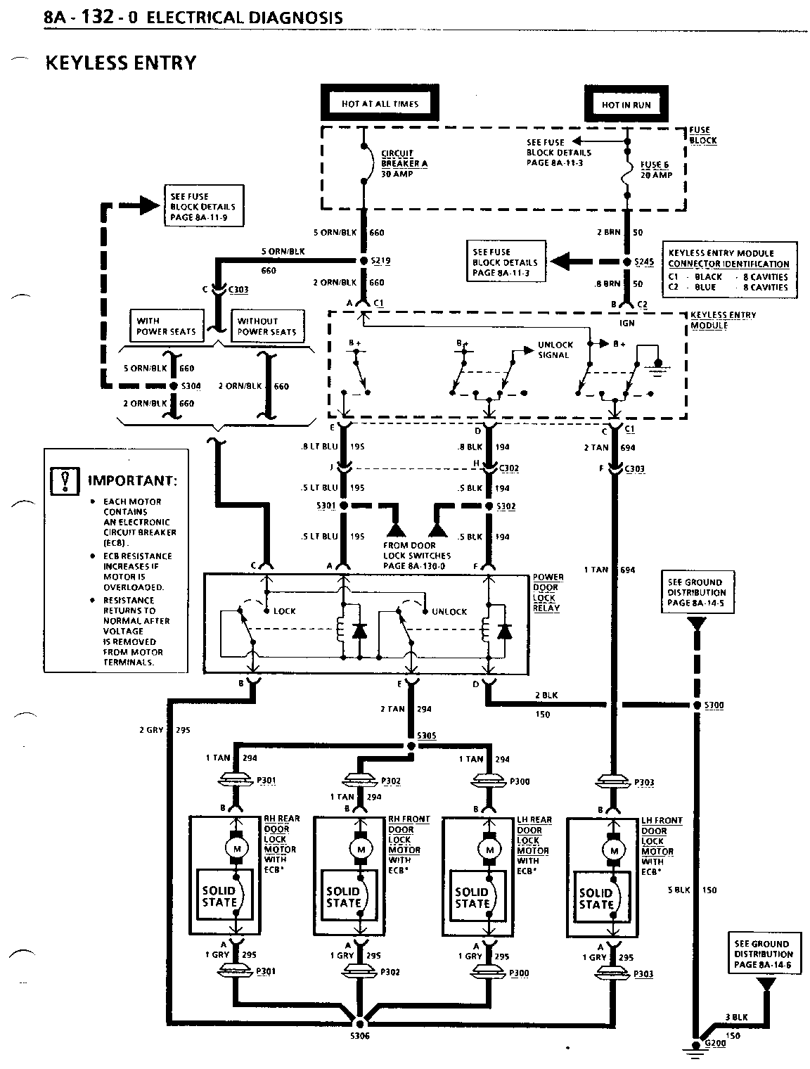
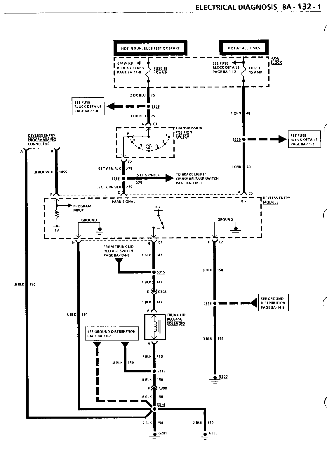
Vehicle's built with VIN numbers starting with NRlOlOll (Arlington) or NW 103483 (Willow Run) were built with a second design two connector keyless entry module. This module provides all the functions of the Chevrolet Keyless Entry System. In order to diagnose and repair any vehicles with the two connector keyless entry module, use the following Electrical Diagnosis pages: 8A-132-0, 8A-132-1, 8A-132-2 and Accessory pages 9K-5, 9K-6, and 9K-8 to 9K-17.
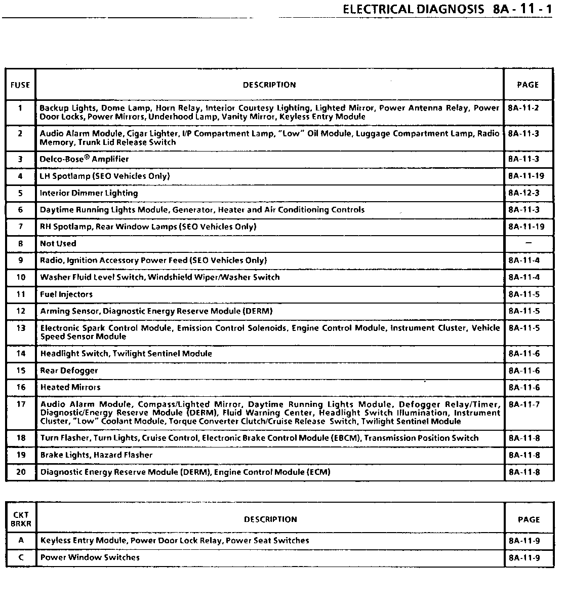
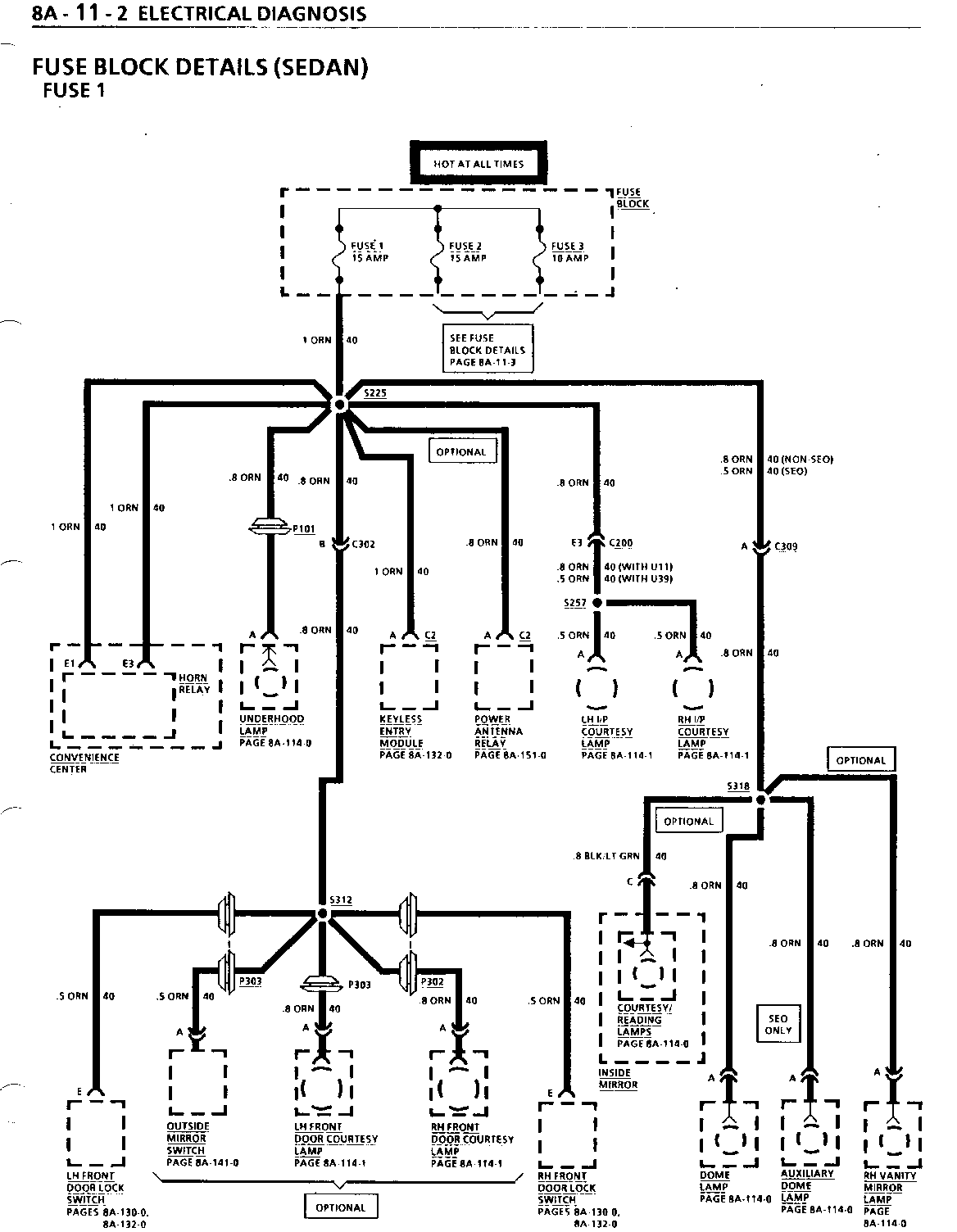
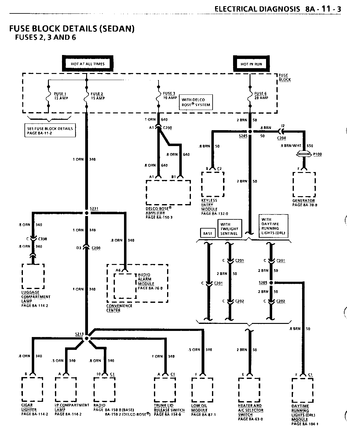
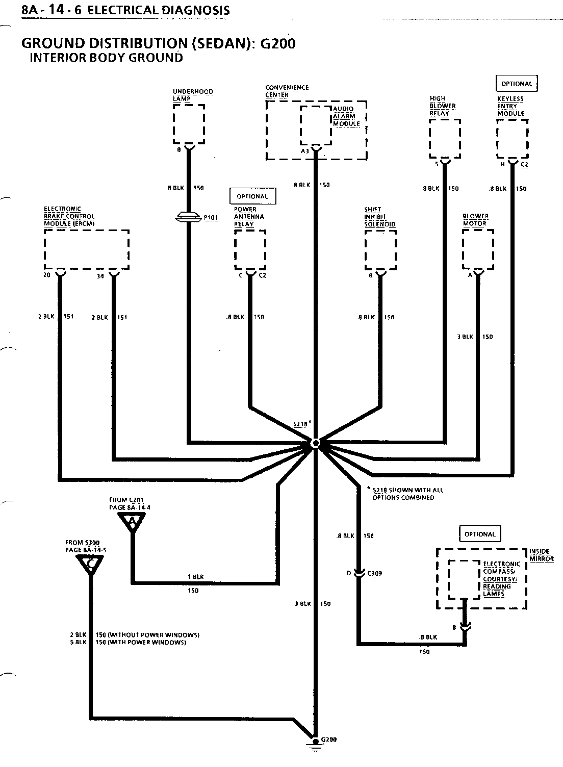
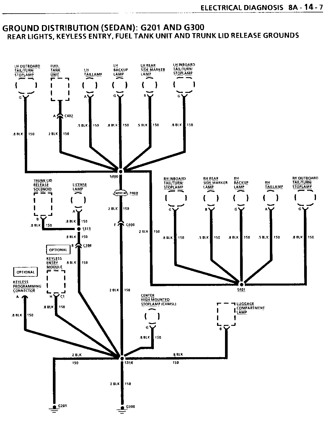
Because of the above change, the following Electrical Diagnosis pages 8A-11-1 8A-11-2, 8A-11-3; 8A-14-6, 8A-14-7; and 8A-112-0, 8A-112-2, 8A-112-3, and 8A-112-5 have been revised. Retain the original service manual pages for early 1992 vehicles that might need service.
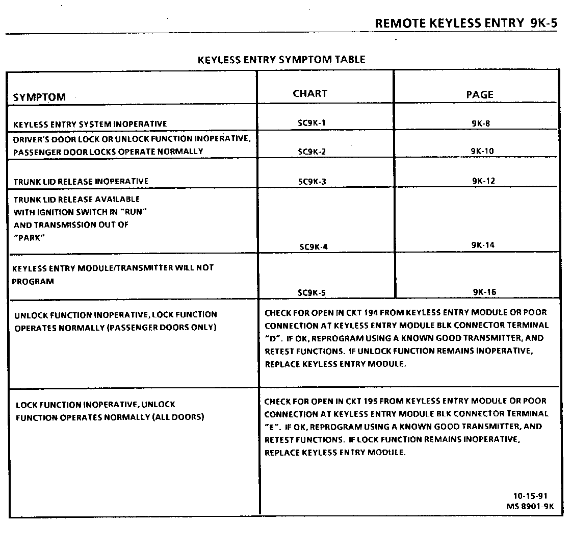
KEYLESS ENTRY SYMPTOM TABLE
SYMPTOM CHART PAGE ------- ----- ----
KEYLESS ENTRY SYSTEM INOPERATIVE SC9K-l 9K-8
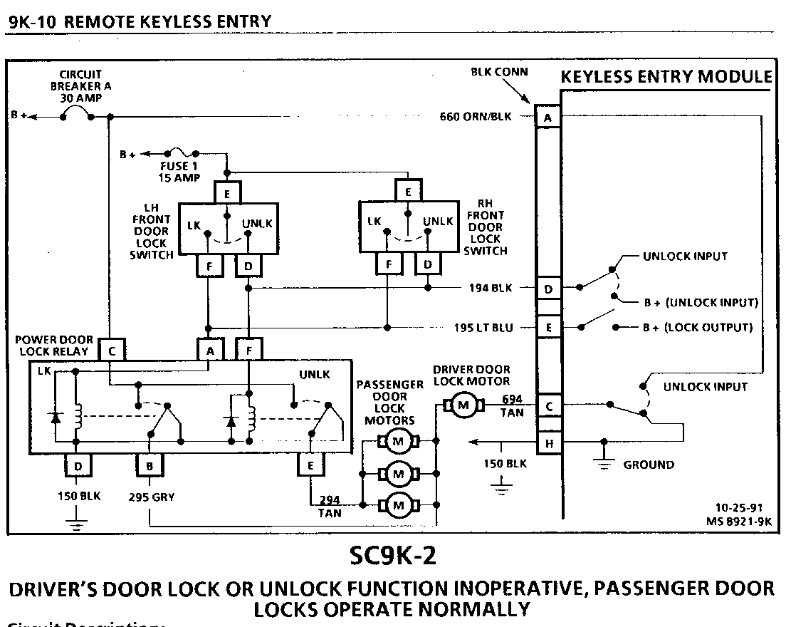
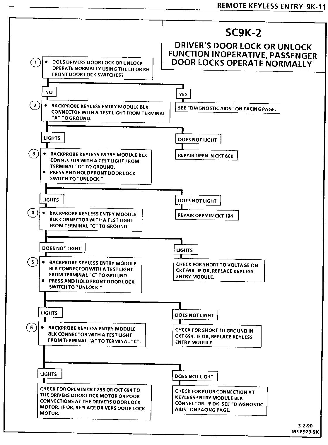
DRIVER'S DOOR LOCK OR UNLOCK FUNCTION INOPERATIVE, PASSENGER DOOR LOCKS OPERATE NORMALLY SC9K-2 9K-10
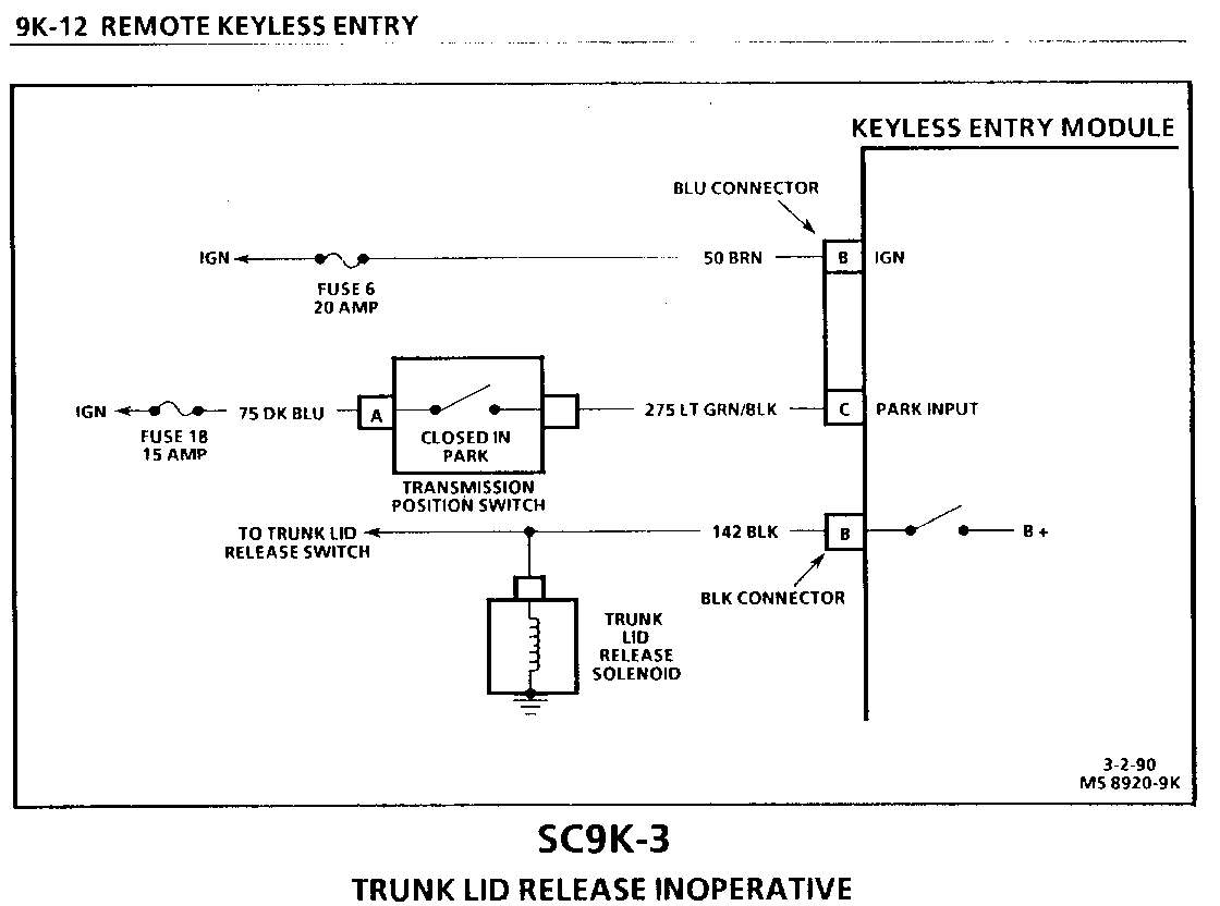
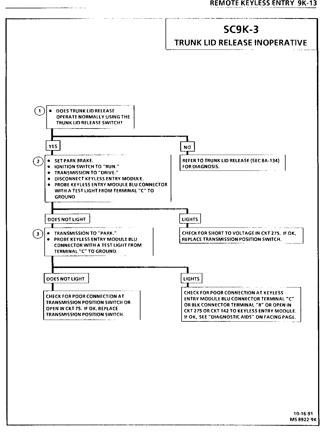
TRUNK LID RELEASE INOPERATIVE SC9K-3 9K-12
TRUNK LID RELEASE AVAILABLE WITH IGNITION SWITCH IN "RUN" AND TRANSMISSION OUT OF -PARK- SC9K-4 9K-14
KEYLESS ENTRY MODULE/TRANSMITTER WILL NOT PROGRAM SC9K-5 9K-16
UNLOCK FUNCTION INOPERATIVE, LOCK FUNCTION CHECK FOR OPEN IN CKT 194 OPERATES NORMALLY (PASSENGER DOORS ONLY) FROM KEYLESS ENTRY MODULE OR POOR CONNECTION AT KEYLESS ENTRY MODULE BLK CONNECTOR TERMINAL "D". IF OK, REPROGRAM USING A KNOWN GOOD TRANSMITTER, AND RETEST FUNCTIONS. IF UNLOCK FUNCTION REMAINS INOPERATIVE, REPLACE KEYLESS ENTRY MODULE.
LOCK FUNCTION INOPERATIVE, UNLOCK CHECK FOR OPEN IN CKT 195 FUNCTION OPERATES NORMALLY (ALL DOORS) FROM KEYLESS ENTRY MODULE OR POOR CONNECTION AT KEYLESS ENTRY MODULE BLK CONNECTOR TERMINAL "E". IF OK, REPROGRAM USING A KNOWN GOOD TRANSMITTER, AND RETEST FUNCTIONS. IF LOCK FUNCTION REMAINS INOPERATIVE, REPLACE KEYLESS ENTRY MODULE.
10-15-91 MS 89O1-9K
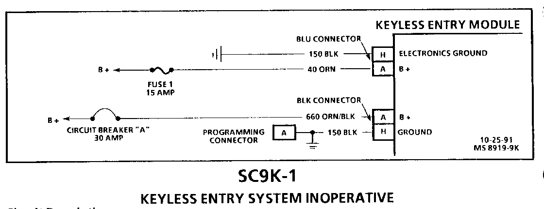
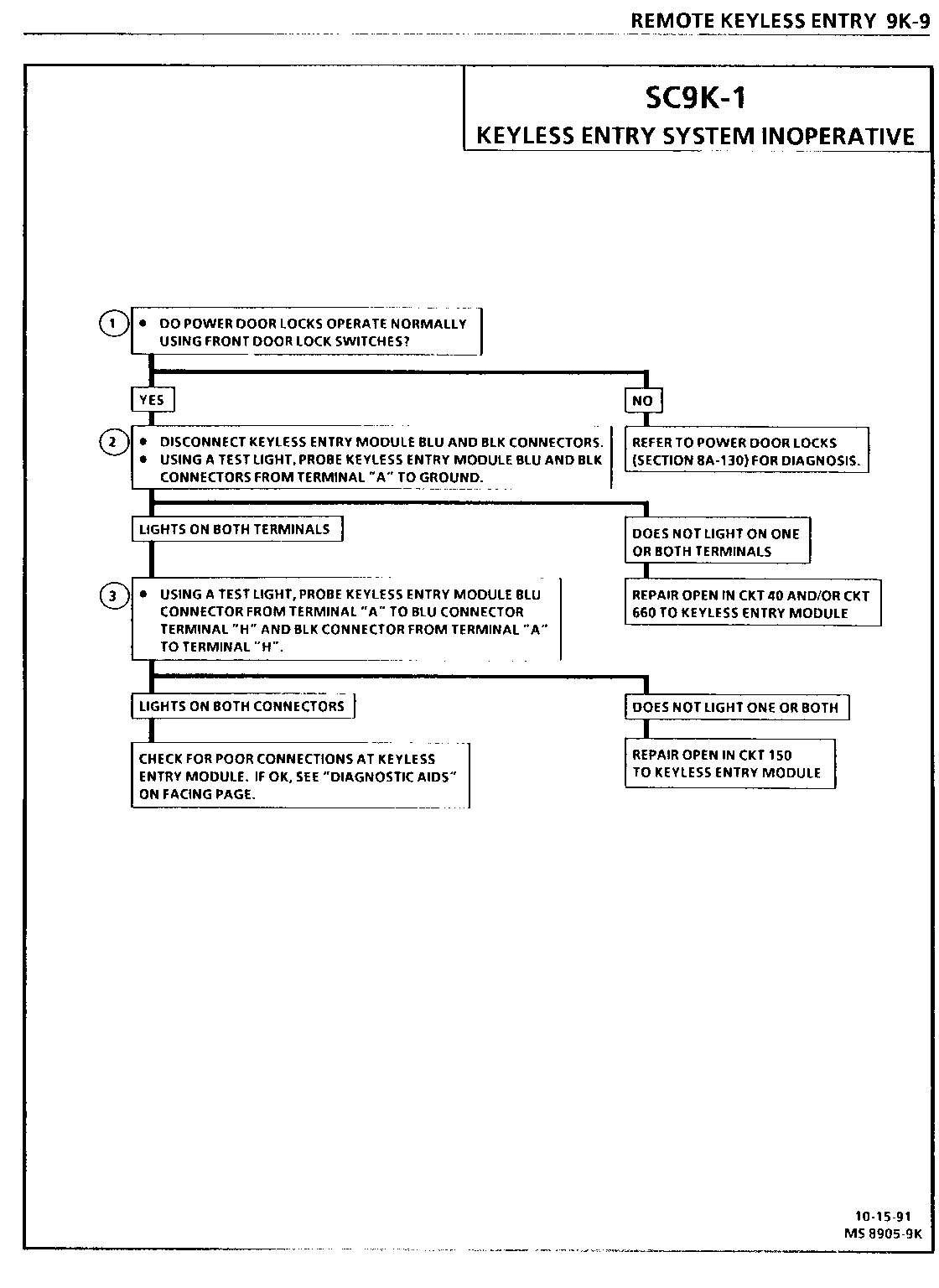
SC9K-1 KEYLESS ENTRY SYSTEM INOPERATIVE --------------------------------
Circuit Description:
Battery voltage is applied to the Keyless Entry Module at all times through Fuse 1 and circuit breaker "A". The Keyless Entry Module is grounded at all times.
Test Description: Number(s) below refer to circled number(s) on the diagnostic chart.
1. Isolate a Power Door lock System fault or a Keyless Entry System fault.
2. Check for battery voltage at the Keyless Entry Module.
3. Check for ground at the Keyless Entry Module.
Diagnostic Aids:
Program a known good transmitter (see procedure on Page 9K-4 in this section), and test the Keyless Entry System. If the Keyless Entry System operates normally, the original transmitter was defective. If the Keyless Entry System is still inoperative, replace the Keyless Entry Module. If a known good transmitter will not program, refer to SC9K-5, Page 9K-16 in this section.
SC9K-2 DRIVER'S DOOR LOCK OR UNLOCK FUNCTION INOPERATIVE, PASSENGER DOOR LOCKS OPERATE NORMALLY ----------------------
Circuit Description:
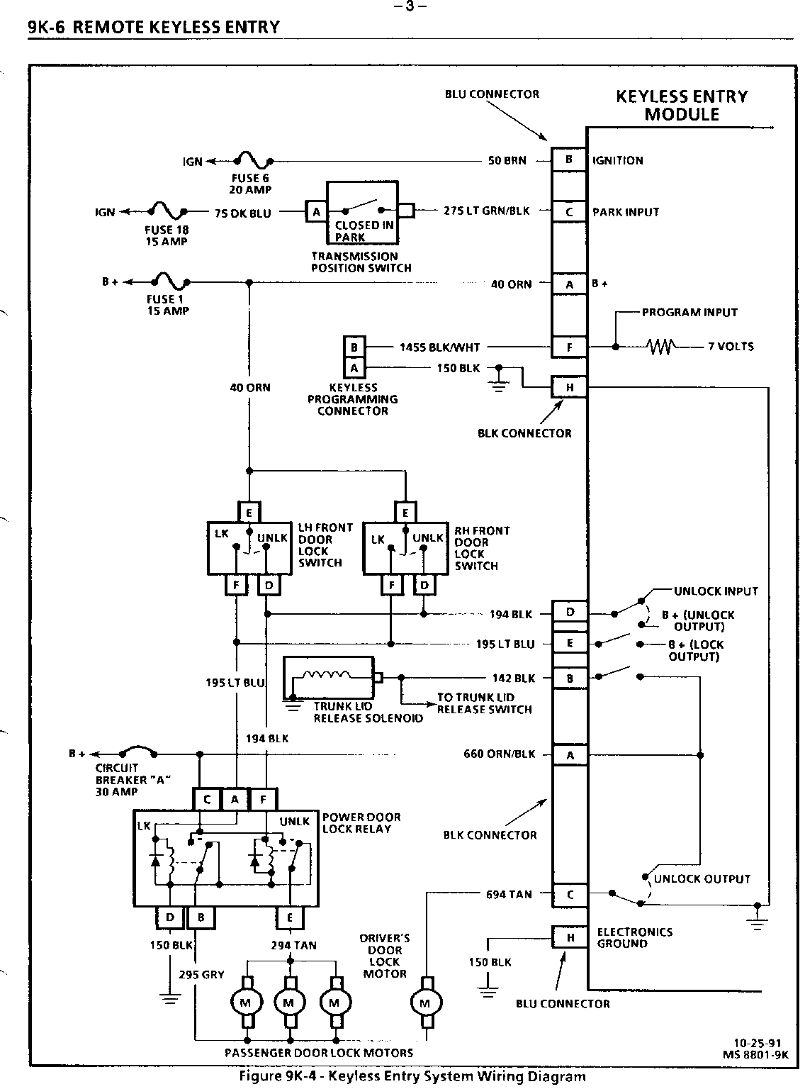
Lock function: Battery voltage is applied through the Power Door lock Relay and CKT 295 to the driver's Door Lock Motor. The driver's Door Lock Motor is grounded through CKT 694 and the Keyless Entry Module. Unlock function: The Keyless Entry Module applies voltage to the driver's Door Lock Motor through CKT 694. The driver's Door Lock Motor is grounded through CKT 295 and the Power Door Lock Relay.
Test Description: Number(s) below refer to circled number(s) on the diagnostic chart.
1. Operating the Door lock Switches will isolate transmitter/receiver problem.
2. Check for battery voltage at the Keyless Entry Module, (driver's Door lock Motor supply voltage).
3. Check for unlock signal at the Keyless Entry Module.
4. Check for voltage on CKT 694. Voltage on CK 694 would prevent the driver's Door Lock Motor from locking.
5. Check that the Keyless Entry Module applies voltage to CKT 694 when an unlock request is present.
6. Check that the Keyless Entry Module grounds CKT 694 to enable a lock request.
Diagnostic Aids:
Program a known good transmitter (see procedure on Page 9K-4 in this section) and test the driver's door lock and unlock functions. If the driver's door lock and unlock functions operate normally, the original transmitter was defective. If the driver's door lock and unlock functions are still inoperative replace the Keyless Entry Module. If a known good transmitter will not program, refer to SC9K-5, Page 9K-16 in this section.
SC9K-3 TRUNK LID RELEASE INOPERATIVE -----------------------------
Circuit Description:
When the Keyless Entry Module senses no voltage on CKT 50 and CKT 275, the trunk lid release function can be activated using the transmitter. When the Keyless Entry Module senses voltage on CKT 50 and CK r r275, (Ignition Switch in "RUN" and Transmission in "PARK") the trunk lid release function can also be activated using the transmitter. When the Keyless Entry Module senses voltage on CKT 50 (Ignition Switch in "RUN") and no voltage on CKT 275 (Transmission not in "PARK") the trunk lid release function cannot be activated by the transmitter.
Test Description: Number(s) below refer to circled number(s) on the diagnostic chart.
1. Determine a Keyless Entry System fault or Trunk Lid Release System Fault.
2. Test the Transmission Position Switch. With Transmission in "DRIVE," the Transmission Position Switch should be open, removing voltage from CKT 275.
3. Test the Transmission Position Switch. With the Transmission in "PARK," the Transmission Position Switch should be closed, applying voltage to CKT 275.
Diagnostic Aids:
Program a known good transmitter (see procedure on Page 9K-4 in this section) and test the trunk lid release function. If the trunk lid release function operates normally, the original transmitter was defective. If the trunk lid release function is still inoperative, replace the Keyless Entry Module. If a known good transmitter will not program, refer to SC9K-5, Page 9K- 16 in this section.
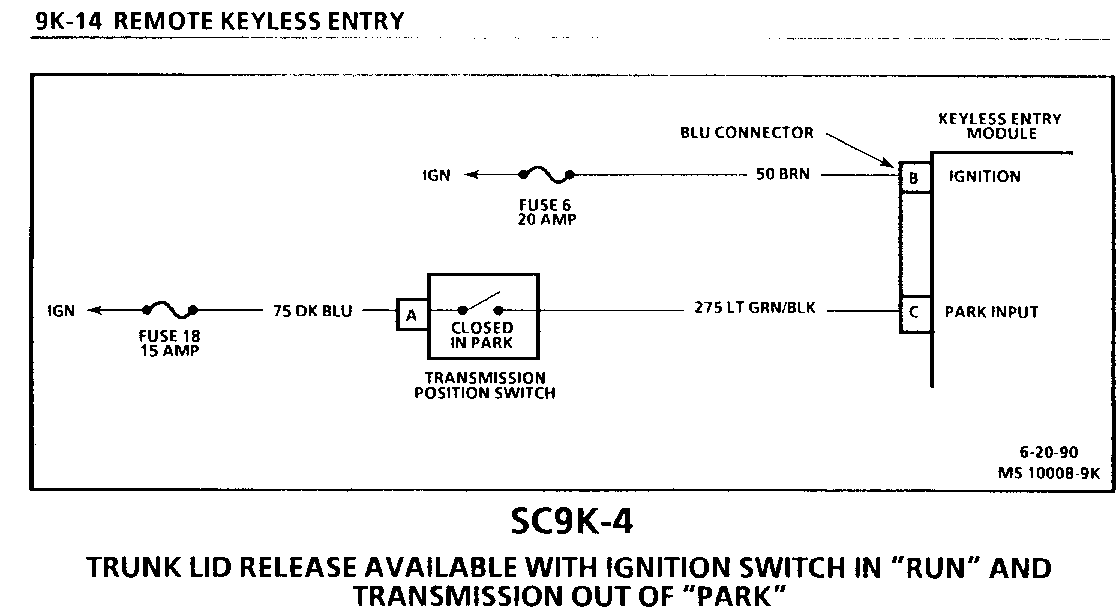
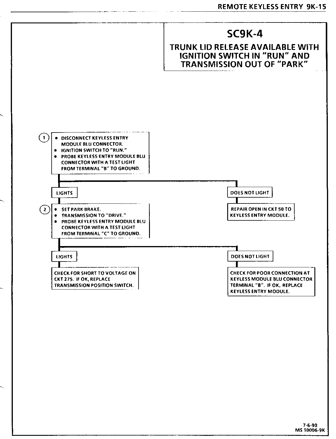
SC9K-4 TRUNK LID RELEASE AVAILABLE WITH IGNITION SWITCH IN "RUN" AND TRANSMISSION OUT OF -PARK" ---------------------------
Circuit Description:
When the Keyless Entry Module senses no voltage on CKT 50 and CKT 275, the trunk lid release function can be activated using the transmitter. When the Keyless Entry Module senses voltage on CKT 50 and CKT 275, (Ignition Switch in "RUN" and Transmission in "PARK") the trunk lid release function can also be activated using the transmitter. When the Keyless Entry Module senses voltage on CKT 50 (Ignition Switch in "RUN") and no voltage on CKT 275 (Transmission not in "PARK") the trunk lid release function cannot be activated by the transmitter.
Test Description: Number(s) below refer to circled number(s) on the diagnostic chart.
1. Check for an ignition input signal to the Keyless Entry Module.
2. Check for a false signal from the Transmission Position Switch or short to voltage on CKT 275.
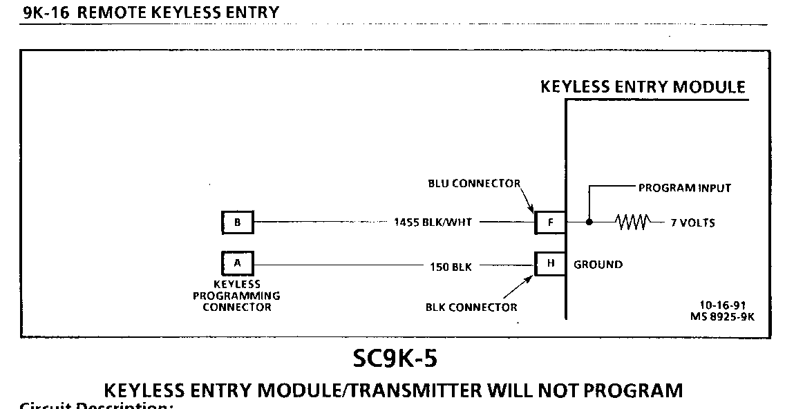
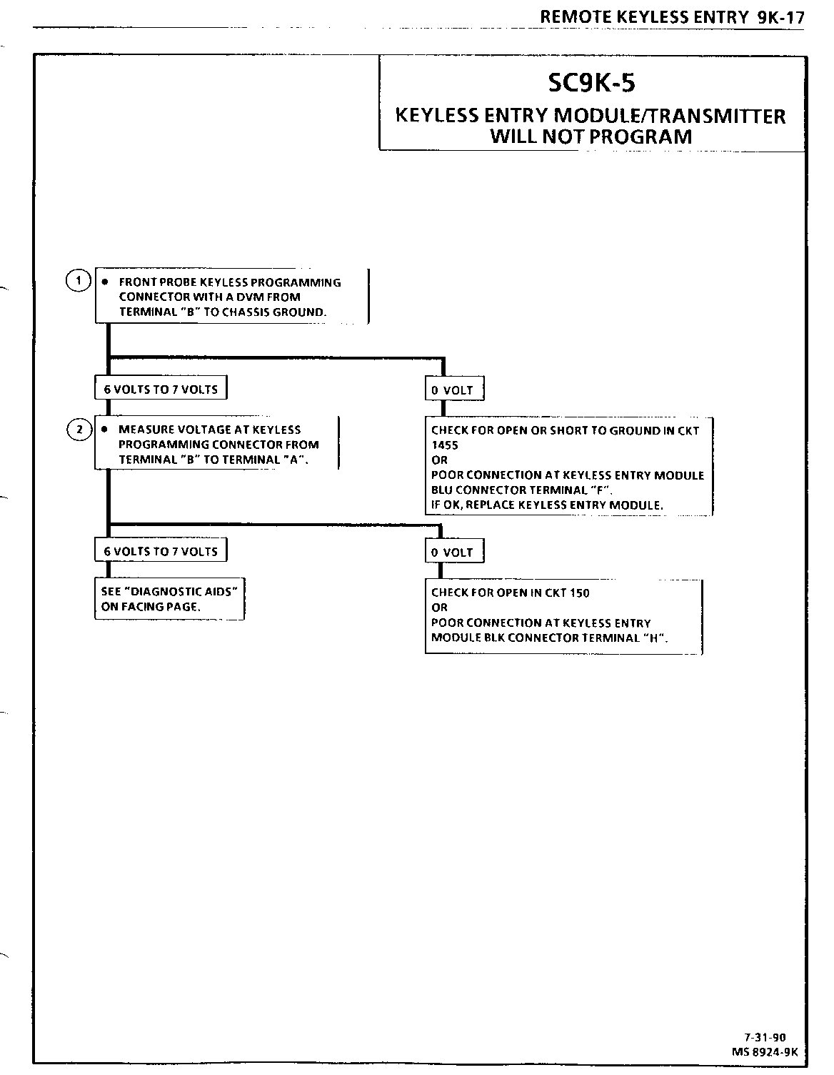
SC9K-5 KEYLESS ENTRY MODULE/TRANSMITTER WILL NOT PROGRAM -------------------------------------------------
Circuit Description:
The Keyless Entry Module applies voltage to CKT 1455. When the Keyless Programming Connector terminals "A" and "B" are shorted together, using a fused jumper, the Keyless Entry Module senses a voltage drop on CKT 1455. The Keyless Entry Module then cycles all Door Lock Motors once. The Keyless Entry Module then waits for input from the transmitter(s) or for the fused jumper to be removed from the Keyless Programming Connector.
Test Description: Number(s) below refer to circled number(s) on the diagnostic chart.
1. Check that the Keyless Entry Module applies voltage to CKT 1455.
2. Check the ground, CKT 150, to the Keyless Entry Module.
Diagnostic Aids:
Program a known good transmitter (see procedure on Page 9K-4 in this section), and test the Keyless Entry System. If the Keyless Entry System operates normally, the original transmitter was defective. If the Keyless Entry Module does not program, using a known good transmitter, replace the Keyless Entry Module.
ELECTRICAL DIAGNOSIS
FUSE DESCRIPTION PAGE ---- ----------- ----
1 Backup Lights, Dome Lamp, Horn Relay, Interior Courtesy Lighting, 8A-11-2 Lighted Mirror, Power Antenna Relay, Power Door Locks, Power Mirrors, Underhood Lamp, Vanity Mirror, Keyless Entry Module
2 Audio Alarm Module, Cigar Lighter, I/P Compartment Lamp, "Low" 8A-11-3 Oil Module, Luggage Compartment Lamp, Radio Memory, Trunk Lid Release Switch
3 Delco-Bose Amplifier 8A-11-3
4 LH Spotlamp (SEO Vehicles Only) 8A-11-19
5 Interior Dimmer Lighting 8A-12-3
6 Daytime Running Lights Module, Generator, Heater and Air 8A-11-3 Conditioning Controls
7 RH Spotlamp, Rear Window Lamps (SEO Vehicles Only) 8A-11-19
8 Not Used -
9 Radio, Ignition Accessory Power Feed (SEO Vehicles Only) 8A-11-4
10 Washer Fluid Level Switch, Windshield Wiper/Washer Switch 8A-11-4
11 Fuel Injectors 8A-11-5
12 Arming Sensor, Diagnostic Energy Reserve Module (DERM) 8A-11-5
13 Electronic Spark Control Module, Emission Control 8A-11-5 Solenoids, Engine Control Module, Instrument Cluster, Vehicle Speed Sensor Module
14 Headlight Switch, Twilight Sentinel Module 8A-11-6
15 Rear Defogger 8A-11-6
16 Heated Mirrors 8A-11-6
17 Audio Alarm Module, Compass/Lighted Mirror, Daytime Running 8A-11-7 Lights Module, Defogger Relay/Timer, Diagnostic/Energy Reserve Module (DERM), Fluid Warning Center, Headlight Switch Illumination, Instrument Cluster, "Low" Coolant Module, Torque Converter Clutch/Cruise Release Switch, Twilight Sentinel Module
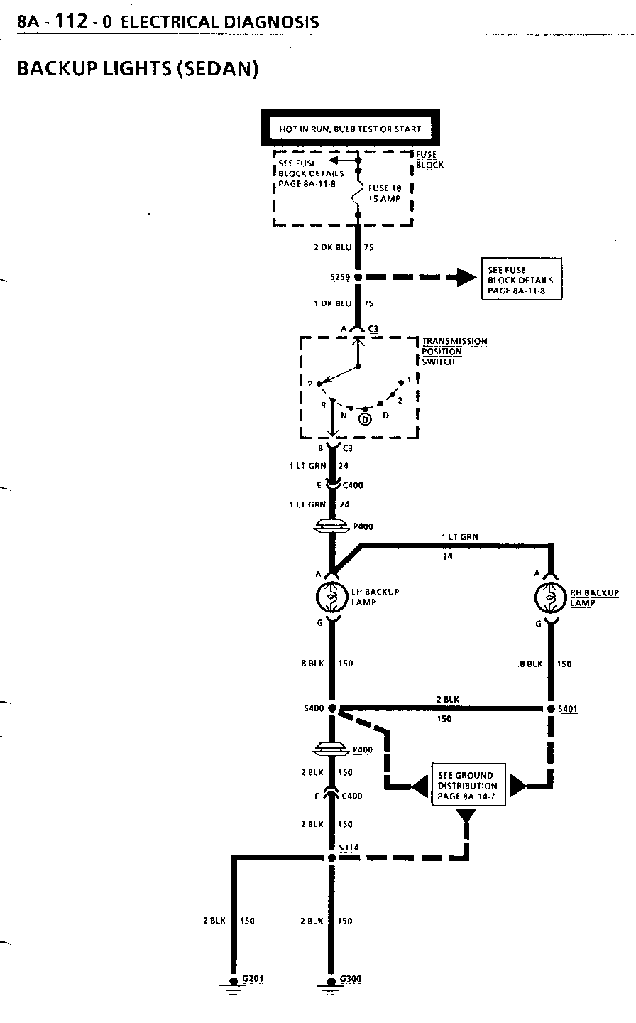
18 Turn Flasher, Turn Lights, Cruise Control, Electronic Brake 8A-11-8 Control Module (EBCM), Transmission Position Switch
19 Brake Lights, Hazard Flasher 8A-11-8
20 Diagnostic Energy Reserve Module (DERM), Engine Control 8A-11-8 Module (ECM)
CKT BRKR DESCRIPTION PAGE ---- ----------- ---- A Keyless Entry Module, Power Door Lock Relay, Power Seat 8A-11-9 Switches
C Power Window Switches 8A-11-9
TROUBLESHOOTING HINTS
(Perform before beginning System Diagnosis)
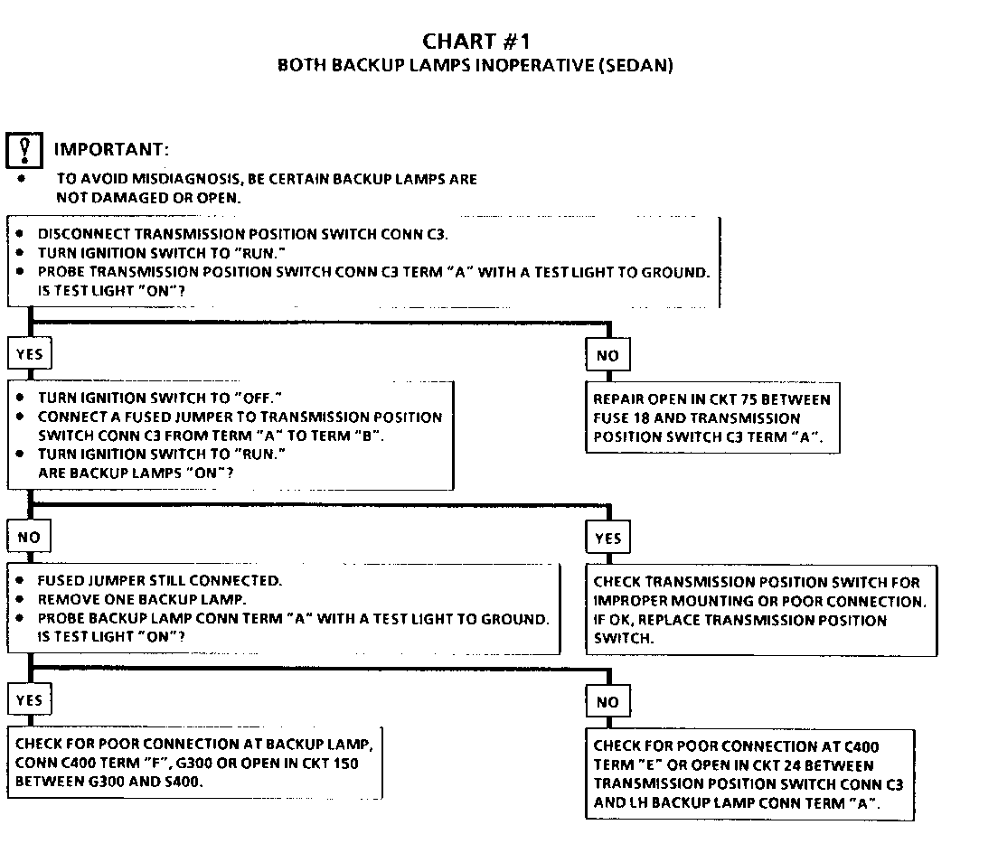
1. Check Fuse 18. If open, check CKT 75 for a short to ground.
2. Check the Backup Lamps for damage to the filament or corrosion between the Backup Lamp and Backup Lamp Socket.
- Refer to System Diagnosis.
SYSTEM DIAGNOSIS
Refer to the Symptom Table for the appropriate diagnostic procedure(s).
BACKUP LIGHTS
COMPONENT LOCATION 201-PG FIG. CONN --------- --------- ------ ---- ---- Fuse Block Mounted to LH/I/P, accessible with LH Front Door Open
LH Backup Lamp LH rear of Vehicle 38,41 57,62
RH Backup Lamp RH rear of Vehicle 38,42 57,63
Transmission Position Switch Near base of Steering Column, 18 28 on Column
C350 (6 cavities) Body Harn to Rear Header Harn, 33 48 202-4 near center of LH "D" Pillar.
C400 (8 cavities) (Sedan) Body Harn to Rear Lamp Harn, in 38 57 202-4 Luggage Compartment on LH Rear Fender
C400 (6 cavities) (Wagon) Body Harn to LH Taillamp Harn, 41 62 202-3 forward of Taillamps
C406 (6 cavities) RH Taillamp Harn to Rear Header Harn, forward of Taillamps 42 63 202-3
G201 Base of LH "A" Pillar, 28 42 behind LH Kickpad
G300 (Sedan) LH Rear Wheelhouse in Luggage 36 54 Compartment
G300 (Wagon) Near center of RH "D" Pillar 33 48
G400 Near center of RH "D" Pillar 34 49
P400 (Sedan) LH rear of Vehicle, in Luggage 38 57 Compartment
P400 (Wagon) LH rear of Vehicle, at Taillamps 41 62
P401 RH rear of Vehicle, at Taillamps 42 63
S259 Body Harn, approx 15 cm from Fuse Block Breakout
S276 (Wagon Only) Body Harn, approx 52 cm from G300 Breakout
S314 (Sedan) Body Harn, approx 9 cm from C308 Breakout
S314 (Wagon) Body Harn, approx 7 cm from C401 Breakout
S400 (Sedan) Rear Lamp Harn, approx 4 cm from C402 Breakout
S400 (Wagon) LH Rear Lamp Harn, approx 12 cm from RH Lower Tail/Turn/Stoplamp Conn Breakout
S401 (Sedan) Rear Lamp Harn, approx 4 cm from RH raillamp Conn Breakout
S401 (Wagon) RH Rear Lamp Harn, approx 12 cm from RH Lower Tail/Turn/Stoplamp Conn Breakout
S406 Rear Header Harn, approx 17 from G303 Breakout
SYMPTOM TABLE
SYMPTOM PROCEDURE PAGE NUMBER ------- --------- ----------- Both Backup Lamps inoperative (Sedan). Chart #1 8A-1 12-3 One Backup Lamp inoperative (Sedan). Chart #2 8A-1 12-4 Backup Lamps "ON" at all times. Chart #3 8A-1 12-4 Both Backup Lamps inoperative (Wagon). Chart #4 8A-1 12-4 One Backup Lamp inoperative (Wagon) Chart #5 8A-1 12-4
CIRCUIT OPERATION
Voltage is applied to the Transmission Position Switch with the Ignition Switch in "RUN," "BULB TEST,"or "START." When the Transmission is shifted into "Reverse," the Transmission Position Switch closes the circuit and voltage is applied to the Backup Lamps. The Lamps are permanently grounded.
KEYLESS ENTRY
COMPONENT LOCATION 201-PG FIG. CONN --------- -------- ------ --- ---- Fuse Block Mounted to LH I/P, accessible with LH Front Door open 14 24
Keyless Entry Module Front of Luggage Compartment, attached to Rear Shelf 36 53 Keyless Entry Programming Conn LH Rear Luggage Compartment 37 56
LH Front Door Lock Motor LH Front Door 28 42
LH Rear Door Lock Motor LH Rear Door 30 44
Power Door lock Relay At base of LH "A" Pillar, behind 26 40 202-11 Kickpad
RH Front Door Lock Motor RH Front Door 29 43
RH Rear Door Lock Motor RH Rear Door 31 45
Transmission Position Near Base of Steering Column, or Switch Column 18 28
Trunk Lid Release Solenoid Bolted to Trunk Lid 37 55
C302 (I 0 cavities) Cross Car Harn to Body Harn, behind 28 42 202-3 LH Kickpad at base of "A" Pillar
C303 (6 cavities) Cross Car Harn to Body Harn, behind 28 42 202-3 LH Kickpad at base of "A" Pillar
C308 (4 cavities) Body Harn to Trunk Lid Harn, upper 37 55 202-4 LH side of Luggage Compartment
G200 Base of LH "A" Pillar, behind LH 28 42 Kickpad
G201 Base of LH "A" Pillar, behind LH 28 42 Kickpad
G300 LH Rear Wheelhouse in Luggage 36 54 Compartment
P300 Between LH Rear Door and "B" Pillar 30 44
P301 Between RH Rear Door and "B" Pillar 31 45
P302 Between RH Front Door and "A" Pillar 29 43
P303 Between LH Front Door and "A" Pillar 28 42
S218 Body Harn, approx 4 cm from G200 Breakout
S219 Body Harn, approx 26 cm from C101 Breakout
S225 Body Harn, approx 18 cm from Fuse Block Breakout
S245 Body Harn, approx 4 cm from Arming Sensor Conn Breakout
S259 Body Harn, approx 15 cm from Fuse Block Breakout
S263 Body Harn, approx 18 cm left of C302
3300 Cross Car Harn, approx 12 cm from C302 Breakout
S301 Cross Car Harn, approx 4 cm from Power Door Lock Relay Conn Breakout
S302 Cross Car Harn, approx 16 cm from C302 Breakout
S304 Cross Car Harn, approx 8 cm from Power Door Lock Relay Conn Breakout
S305 Cross Car Harn, approx 4 cm from C302 Breakout
S306 Cross Car Harn, approx 12 cm from Power Door Lock Relay Conn Breakout
S313 Trunk Lid Harn, approx 4 cm from License Lamp Conn Breakout
S314 Body Harn, approx 9 cm from C308 Breakout
S315 Body Harn, approx 8 cm from Center High Mounted Stoplamp Conn Breakout
SYSTEM DIAGNOSIS
Refer to SECTION 9K for diagnosis and programming of the Keyless Entry System.

General Motors bulletins are intended for use by professional technicians, not a "do-it-yourselfer". They are written to inform those technicians of conditions that may occur on some vehicles, or to provide information that could assist in the proper service of a vehicle. Properly trained technicians have the equipment, tools, safety instructions and know-how to do a job properly and safely. If a condition is described, do not assume that the bulletin applies to your vehicle, or that your vehicle will have that condition. See a General Motors dealer servicing your brand of General Motors vehicle for information on whether your vehicle may benefit from the information.
