GM Service Manual Online
For 1990-2009 cars only

The Evaporative Emission (EVAP) control system used on all vehicles is the charcoal canister storage method. This method transfers fuel vapor from the fuel tank to an activated carbon (charcoal) storage device (canister) to hold the vapors when the vehicle is not operating. When the engine is running, the fuel vapor is purged from the carbon element by intake air flow and consumed in the normal combustion process.

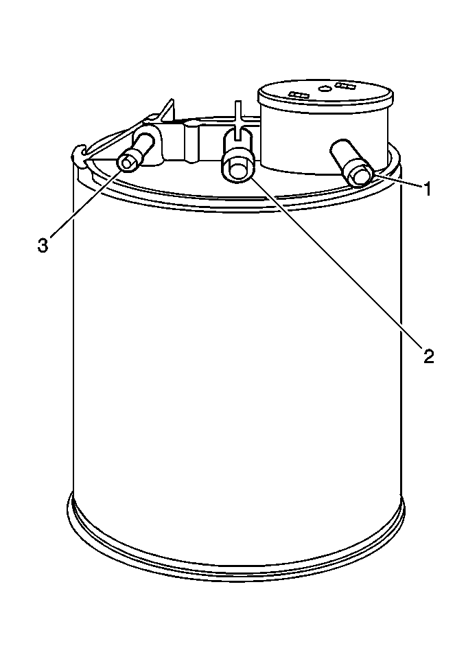
Fuel Vapor Canister


Object Number: 13585  Size: MH
(1)Tank Tube
(2)Air Tube (Fresh Air Inlet)
(3)Purge Tube

The Evaporative Emission (EVAP) control system uses a 1500 cc charcoal canister to absorb fuel vapors from the gas tank.

When gasoline vapor builds enough to overcome the spring tension of the EVAP pressure control valve, the vapor will flow to the canister where it is absorbed and stored by the charcoal. Under certain operating conditions the PCM will command the purge solenoid valve to open. This allows the vapor to flow into the intake manifold for combustion.

This system has a remote mounted canister purge control solenoid valve. The PCM operates this solenoid valve to control vacuum to the canister. Under cold engine or idle conditions, the solenoid valve is closed, which prevents vacuum from being applied to the canister. The PCM activates (or opens) the solenoid valve and allows purge under the following conditions:
    • Engine is warm.
    • After the engine has been running a specified period of time.
    • Above a specified road speed.
    • Above a specified throttle opening.

EVAP Pressure Control Valve


Object Number: 13645  Size: SH
(1)Control Tube
(2)Tube to Canister
(3)Umbrella Valve
(4)Restriction
(5)Tube to Fuel Tank
(6)Diaphragm
(7)Diaphragm Spring

Evaporative Emission (EVAP) Pressure Control Valve

This system uses an in-line EVAP pressure control valve as a pressure relief valve. When vapor pressure in the tank exceeds approximately 5 kPa (.7 psi) the diaphragm valve opens, allowing vapors to vent to the canister. A 1.14 mm (0.045 inch) orifice in the passage leading to the canister tube causes pressure to drop slowly, preventing the valve from oscillating (buzzing). When the tank pressure drops below 5 kPa (.7 psi), the valve closes causing vapors to be held in the fuel tank.

Results of Incorrect Operation

    • Poor idle, stalling and poor driveability can be caused by the following:
       - Inoperative purge solenoid valve.
       - Damaged canister.
       - Hoses split, cracked and, or not connected to the proper tubes.
    • Evidence of fuel loss or fuel vapor odor can be caused by:
       - Liquid fuel leaking from fuel lines.
       - Cracked or damaged canister.
       - Inoperative canister control valve.
       - Vacuum hoses that are:
   - Disconnected.
   - Mis-routed-routed.
   - Kinked.
   - Deteriorated or damaged vapor hoses.

If the solenoid valve is open, or is not receiving power, the canister can purge to the intake manifold at the incorrect time. This can allow extra fuel during warm-up, which can cause rough or unstable idle.

EVAP Vacuum Switch


Object Number: 13498  Size: SH

EVAP Purge Vacuum Switch

The EVAP Purge Vacuum Switch is used by the PCM to monitor EVAP canister purge solenoid operation and purge system integrity. The EVAP Purge Vacuum Switch should be closed to ground with no vacuum present (0% EVAP Purge PWM). With EVAP Purge PWM at 25% or greater, the EVAP Purge Vacuum Switch should open.

An incorrect EVAP Purge system flow should set a DTC P0441. A continuous purge condition with no purge commanded by the PCM should set a DTC P1441. Refer to Evaporative Emission (EVAP) Control System for a complete description of the EVAP system.

The Evaporative Emission (EVAP) canister purge solenoid valve and the EVAP Vacuum switch diagnosis is covered in the following DTCs:

    • P0441
    • P0443
    • P1441

EVAP Control System Schematic


Object Number: 30073  Size: SH
(1)Throttle Body
(2)EVAP Solenoid Valve
(3)EVAP Vacuum Switch
(4)EVAP Canister
(5)EVAP Pressure Control Valve
(6)Floating Roll-Over Valve
(7)Fuel Tank

Visual Check of EVAP Canister

If cracked or damaged, replace EVAP canister.

Evaporative Emission (EVAP) Pressure Control Valve

With a hand vacuum pump, apply approximately 51 kPa (15 in. Hg) to the control vacuum tube. After ten seconds, there should be at least 17 kPa (5 in. Hg) vacuum remaining. Be sure the hand vacuum pump being used does not have an internal leak and the hose connections to control vacuum tube and pump are secure. If after 10 seconds there is less than 17 kPa (5 in. Hg) vacuum, the valve must be replaced.

With 51 kPa (15 in.  Hg) vacuum still applied to the control vacuum tube, attach a short piece of hose to the valves tank tube side. Blow into the tube. You should feel the air pass through the valve. If air does not pass through, the valve must be replaced.