Removal Procedure
Tools Required
J 37088-A, tool set, Fuel Line Quick-Connect Separator

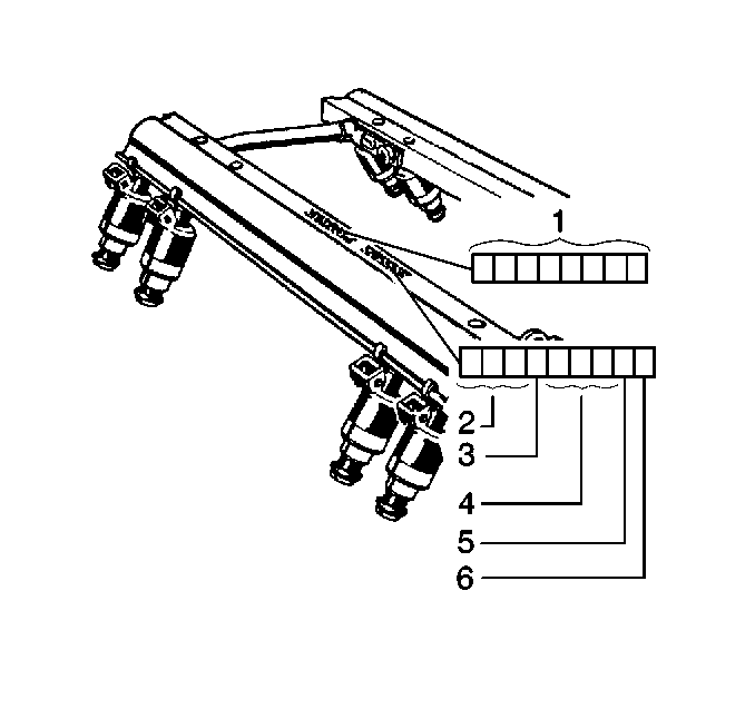
An eight digit identification number (1) is stamped on the fuel rail assembly. Refer to this model identification number if servicing or part replacement is required.
The nine digit number stamped on the fuel rail assembly indicates the day (2) and year (3) that the fuel rail was built, the plant code (4), the shift ID (5), and the source code (6).
- Disconnect the negative battery cable.
- Relieve the fuel system pressure. Refer to the Fuel Pressure Relief Procedure.
- Remove the resonator.
- Before removal, clean the fuel rail assembly with a spray type engine cleaner, GM X-30A or equivalent, if necessary. Follow the package instructions. Do Not soak fuel rails in liquid cleaning solvent.
- Disconnect the quick-connect fittings from the fuel rail. Refer to Servicing Quick-Connect Fittings.
- Disconnect the vacuum lines from the fuel pressure regulator and the EVAP canister purge solenoid.
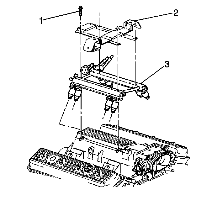
- Disconnect the electrical harness and cables from the routing clips on the resonator bracket (2).
- Remove the resonator bracket (2).
- Disconnect the electrical connectors from the fuel injectors. Identify the connectors to their corresponding injectors to ensure correct sequential injector firing order after reassembly.
- Remove the fuel rail assembly (3).
- Remove the injector lower O-ring seal (brown) from the spray tip end of each injector.
- Discard the O-ring seals. Save the O-ring backups.

Notice:
• Use care when removing the fuel rail assembly in order to prevent
damage to the injector electrical connector terminals and the injector spray
tips. When the fuel rail is removed, support the fuel rail in order to avoid
damaging the fuel rail components. • Cap the fittings and plug the holes when servicing in order to
prevent dirt and other contaminants from entering open pipes and passages. • The upper and lower O-rings are different colors (black and brown).
Install the black O-ring in the upper position on the injector. Install the
brown O-ring in the lower position on the injector. The O-rings are the same
size but are made of different materials.
Installation Procedure
- Lubricate the new lower injector O-ring seals (brown).
- Install the new O-ring seals on the spray tip end of each injector.
- Install the fuel rail assembly (3) to the intake manifold.
- Install the resonator bracket (2).
- Install the fuel rail and resonator bracket attaching bolts (1).
- Install the injector electrical connectors.
- Install the electrical harness and cables into the routing clips on the resonator bracket (2).
- Connect the vacuum lines to the fuel pressure regulator and the EVAP canister purge solenoid.
- Connect the quick-connect fittings to the fuel rail fuel pipes. Refer to Servicing Quick-Connect Fittings.
- Tighten the fuel filler cap.
- Connect the negative battery cable.
- Inspect for leaks.

Important: The fuel injector lower O-ring uses a nylon collar, called the O-ring backup, to properly position the O-ring on the injector. Always reinstall the O-ring backup, or the sealing O-ring may move on the injector when installing the fuel rail and result in a possible vacuum leak.
Tighten
Tighten the fuel rail and resonator bracket attaching bolts to 10 N·m
(89 lb in).
| • | Install each connector on the proper injector to ensure correct sequential injector firing order. |
| • | Rotate the injectors as required in order to avoid stretching the wire harness. |
| 12.1. | Turn the ignition switch ON for 2 seconds. |
| 12.2. | Turn the ignition switch OFF for 10 seconds. |
| 12.3. | Turn the ignition switch ON. |
| 12.4. | Check for fuel leaks. |
