For 1990-2009 cars only
Removal Procedure
- Remove the PCM from the mounting bracket, refer to Powertrain Control Module Replacement/Programming
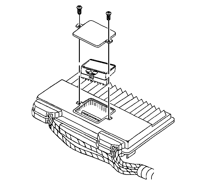
- Remove the knock sensor module access cover.
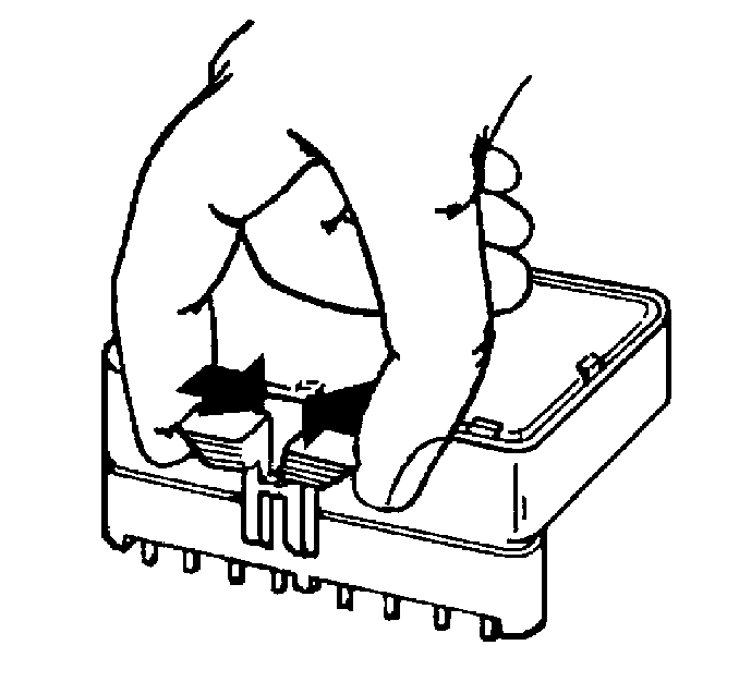
- Remove the knock sensor module.
Notice: In order to prevent possible Electrostatic Discharge damage to the PCM or KS module, do not touch the connector pins or soldered components on the circuit board. Do not remove the integrated circuit boards from the carrier.


Notice: Do not touch the connector pins or soldered components on the circuit board in order to prevent possible electrostatic discharge (ESD) damage to the PCM.
Installation Procedure
- Install the knock sensor module.
- Install the access cover.
- Install the PCM to the mounting bracket, refer to Powertrain Control Module Replacement/Programming

Notice: Do not touch the connector pins or soldered components on the circuit board in order to prevent possible electrostatic discharge (ESD) damage to the PCM.

