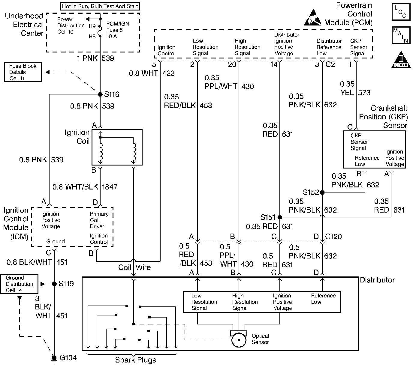
Circuit Description
The distributor ignition system provides two timing inputs to the PCM, a high resolution signal (180 pulses per crankshaft revolution) and a low resolution signal (4 pulses per crankshaft revolution). One of the PCMs uses for these signals is to calculate spark timing. This timing signal is sent to the ignition coil module on the IC circuit. Each pulse on the IC circuit triggers the coil module to fire the ignition coil. The secondary ignition voltage then travels through the distributor to the spark plug. The IC signal voltage ranges from about 0.5 volt to 4.5 volts.
Conditions for Setting the DTC
The PCM detects voltage on the IC circuit in excess of 4.6 volts during cranking.
Action Taken When the DTC Sets
| • | The PCM will illuminate the Malfunction Indicator Lamp (MIL) when the diagnostic runs and fails. |
| • | The PCM will record operating conditions at the time the diagnostic fails. This information will be stored in the Freeze Frame and/or Failure Records. |
| • | The injector will be disabled for the entire ignition cycle. |
Conditions for Clearing the MIL/DTC
| • | The PCM will turn the MIL OFF after three consecutive drive trips that the diagnostic runs and does not fail. |
| • | A last test failed (Current DTC) will clear when the diagnostic runs and does not fail. |
| • | A History DTC will clear after forty consecutive warm-up cycles, if no failures are reported by this or any other emission related diagnostic. |
| • | PCM battery voltage is interrupted. |
| • | Using a Scan tool. |
Diagnostic Aids
Using Freeze Frame and/or Failure Records data may aid in locating an intermittent condition. If the DTC cannot be duplicated, the information included in the Freeze Frame and/or Failure Records data can be useful in determining how many miles since the DTC set. The Fail Counter and Pass Counter can also be used to determine how many ignition cycles the diagnostic reported a pass and/or a fail. Operate vehicle within the same freeze frame conditions (RPM, load, vehicle speed, temperature etc.) that were noted. This will isolate when the DTC failed. For intermittents, refer to Symptoms .
Test Description
Number(s) below refer to step numbers on the diagnostic table.
Step | Action | Value(s) | Yes | No |
|---|---|---|---|---|
1 | Was the Powertrain On-Board Diagnostic (OBD) System Check performed? | -- | ||
2 | Attempt to start the engine. Does the engine start? | -- | Go to Diagnostic Aids | |
Is the voltage within the range shown? | 1.0-4.0 V | |||
4 |
Is the test light ON? | -- | ||
5 | Repair the IC circuit. Is the action complete? | -- | -- | |
6 | Repair the open Ignition Coil Module ground circuit. Is the action complete? | -- | -- | |
7 | Replace the faulty Ignition Coil Module. Is the action complete? | -- | -- | |
8 |
Does the scan tool indicate that this test ran and passed? | -- | ||
9 | Using the scan tool, select Capture Info, Review Info. Are any DTCs displayed that have not been diagnosed? | -- | Go to the applicable DTC table | System OK |
