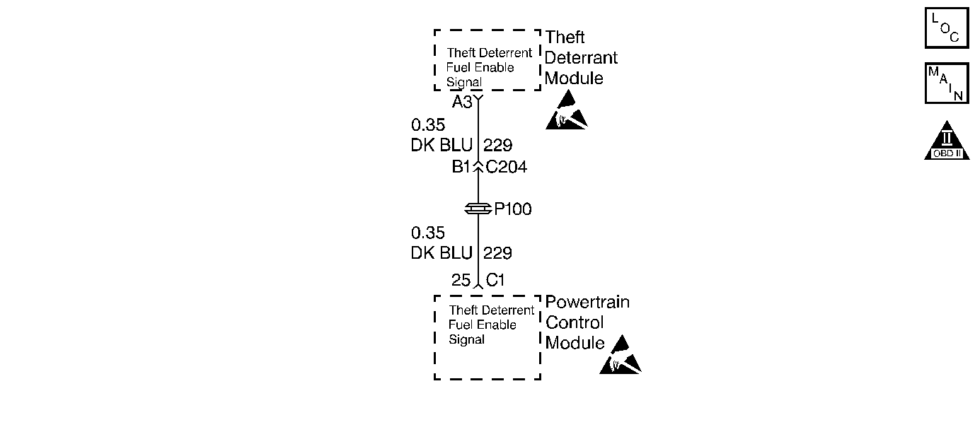
Circuit Description
The system is designed to disable vehicle operation if the incorrect key or starting procedure is used. The theft deterrent module enables the crank circuit to the starter and sends a signal to the PCM if the correct key is being used. If the proper signal does not reach the PCM on the fuel enable circuit, the PCM will not pulse the injectors ON and thus not allow the vehicle to continue to operate, even if the crank circuit is bypassed. The proper signal is between 40-60 Hz and is measured using the DC scale on the DVM.
Conditions for Setting the DTC
| • | The Engine is running or cranking. |
| • | The PCM does not receive the correct signal from the Theft Deterrent Module. |
| • | Condition present for 1.7 seconds. |
Action Taken When the DTC Sets
| • | DTC P1626 will be stored in the PCM memory when the diagnostic runs and fails. |
| • | The Malfunction Indicator Lamp (MIL) will not illuminate. |
| • | The PCM will record operating conditions at the time the diagnostic fails. This information will be stored in Failure Records. |
| • | Engine will start and then stall or engine will not crank. |
Conditions for Clearing the MIL/DTC
| • | A history DTC will clear after 40 consecutive warm-up cycles, if no failures are reported by this or any other non-emission related diagnostic. |
| • | A last test failed (Current DTC) will clear when the diagnostic runs and does not fail. |
| • | PCM battery voltage is interrupted. |
| • | Using a scan tool. |
Diagnostic Aids
| • | If the engine starts and then stalls, indicates that the portion of the theft deterrent module, which generates the signal to the PCM is not operating or circuit 229 is open or shorted to ground. If the theft deterrent module is found to be OK, as determined from service category Electrical or Control Module Circuits, the PCM may be at fault, but this is not a likely condition. |
| • | Using Freeze Frame and/or Failure Records data may aid in locating an intermittent condition. If the DTC cannot be duplicated, the information included in the Freeze Frame and/or Failure Records data can be useful in determining how many miles since the DTC set. The Fail Counter and Pass Counter can also be used to determine how many ignition cycles the diagnostic reported a pass and/or a fail. Operate vehicle within the same freeze frame conditions (RPM, load, vehicle speed, temperature etc.) that were noted. This will isolate when the DTC failed. |
| • | Refer to Symptoms . |
Test Description
Number(s) below refer to step numbers on the diagnostic table.
-
If DTC P1626 is stored, and the engine will not crank, indicates that there is a theft deterrent system problem or an incorrect key or starting procedure is being used. For any test that requires probing the PCM or a component harness connector, must use the Connector Test Adapter Kit J 35616-A. Using this kit will prevent damage to the harness connector terminals.
-
If the engine does not crank indicates there is a problem with the theft deterrent module.
-
This determines if the theft deterrent module is capable of sending a signal to the PCM.
Step | Action | Value(s) | Yes | No | ||||||
|---|---|---|---|---|---|---|---|---|---|---|
1 | Was the Powertrain On-Board Diagnostic (OBD) System Check performed? | -- | ||||||||
2 | Crank the engine. Does the engine start and run? | -- | ||||||||
3 | Does the engine crank? | -- | Go to Service Category Theft Deterrent Systems | |||||||
4 |
Is the hertz within the range specified in the values column? | 40-60Hz | ||||||||
5 | Check circuit 229 for the following:
Was a condition found and corrected? | -- | ||||||||
6 | Replace the Theft Deterrent Module, Refer to Service Category Theft Deterrent Systems . Is the repair completed? | -- | -- | |||||||
7 | Inspect the PCM connector C1-25 for good terminal tension. Did the terminal require a repair? | -- | ||||||||
8 |
Important: Replacement PCM must be programmed. Refer to Powertrain Control Module Replacement/Programming . Replace the PCM. Is the action complete? | -- | -- | |||||||
9 |
Does the scan tool indicate that this test ran and passed? | -- | ||||||||
10 | Using the scan tool, select Capture Info, Review Info. Are any DTCs displayed that have not been diagnosed? | -- | Go to the applicable DTC table | System OK |
